Ultra-dense wavelength division multiplexing system and method

A wavelength division multiplexing and ultra-dense technology, applied in the field of optical communication, achieves the effect of simple implementation and easy promotion and use

Active Publication Date: 2012-07-04
ZTE CORP
View PDF6 Cites 12 Cited by
  • Summary
  • Abstract
  • Description
  • Claims
  • Application Information

AI Technical Summary

Problems solved by technology

[0005] The present invention provides an ultra-dense wavelength division multiplexing system and method to solve th

Method used


Image

  • Ultra-dense wavelength division multiplexing system and method
  • Ultra-dense wavelength division multiplexing system and method
  • Ultra-dense wavelength division multiplexing system and method

Examples


Example

[0062] Application example 1

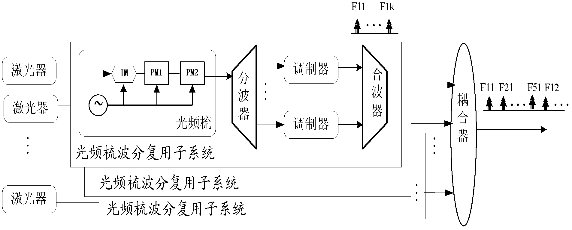
[0063] like figure 2 Shown is an ultra-dense wavelength division multiplexing system composition diagram for this application example.

[0064]The system includes five optical frequency comb wavelength division multiplexing subsystems for outputting multiplexed signals, couplers for interleaving and multiplexing the multiplexed signals output by the five optical frequency comb wavelength division multiplexing subsystems, and five There are two lasers, the output signal of each laser is the seed light source of an optical frequency comb wavelength division multiplexing subsystem, and the frequency interval of the output signal of each laser is 5GHZ.

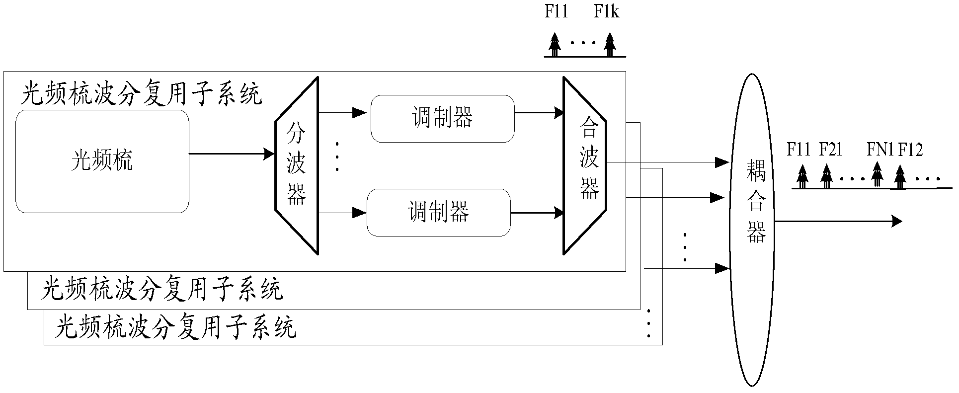
[0065] Among them, each optical frequency comb wavelength division multiplexing subsystem also includes:

[0066] An optical frequency comb, a demultiplexer for separating 27 optical carrier signals from the optical frequency comb, 27 modulators connected to the output ends of the demultiplexer, a...

Example

[0073] Application example 2

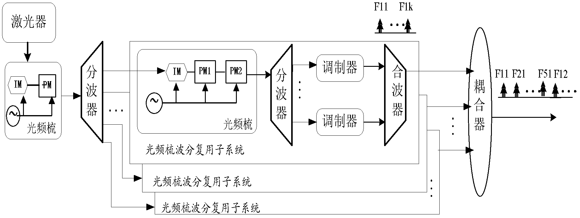
[0074] like image 3 Shown is another UDDWDM system composition diagram for this application example.

[0075] The system includes five optical frequency comb wavelength division multiplexing subsystems for outputting multiplexed signals, and a coupler for interleaving and multiplexing the multiplexed signals output by the five optical frequency comb wavelength division multiplexing subsystems. The system also includes a laser, a seed light source optical frequency comb connected with the laser output end, and a demultiplexer for separating out 5 optical carrier signals from the seed light source optical frequency comb, and the 5 optical carrier signals in the Each optical carrier signal is a seed light source of an optical frequency comb wavelength division multiplexing subsystem, and the frequency interval of the five optical carrier signals is 5GHz. in,

[0076] The configuration of the optical frequency comb wavelength division multiplexin...


PUM


Abstract

The invention provides an ultra-dense wavelength division multiplexing system and a method. The system comprises N optical frequency comb wavelength division multiplexing subsystems and a coupler, wherein the N optical frequency comb wavelength division multiplexing subsystems are used for outputting wave combining signals, and N is an integer which is more than or equal to 2; and the coupler is used for carrying out interleave multiplexing on the wave combining signals output by the N optical frequency comb wavelength division multiplexing subsystems so as to combine into one path of signals. Each optical frequency comb wavelength division multiplexing subsystem comprises an optical frequency comb, a wave separator, K modulators and a wave combiner, wherein the wave separator is used for separating K optical carrier signals from the optical frequency comb, and K is an integer which is more than or equal to 1; the K modulators are connected with the output end of the wave separator; and the wave combiner is connected with the output ends of the K modulators. According to the invention, the ultra-dense wavelength division multiplexing is realized by a plurality of the optical frequency comb wavelength division multiplexing subsystems, and the realization is simple.

Description

technical field [0001] The invention relates to the field of optical communication, in particular to an ultra-dense wavelength division multiplexing system and method. Background technique [0002] In a wavelength division multiplexing (WDM) system of a passive optical fiber network (PON), the optical line terminal OLT needs to generate multi-user downlink data signals. [0003] At present, there are two main methods: one is to integrate multiple channels of distributed feedback lasers and modulators on-chip, and then couple the multiplexed modulated signals into the same fiber for transmission; the other is to use a single optical frequency comb Generates multiple optical carrier signals with equally spaced frequencies, modulates each optical carrier signal, and couples the multiple multiplex modulated signals into the same fiber for transmission. [0004] Both schemes have their own drawbacks. For the first method, since the frequency shift of each laser is a random proc...

Claims


Application Information

Patent Timeline
IPC IPC(8): H04J14/02H04Q11/00
CPCH04J14/00H04J14/0257H04J14/02
Inventor 陈宏伟梁云华何子安苏婕张佩华陈明华谢世钟
Owner ZTE CORP
Why Eureka
Try Eureka