
Induction cooker wire reel and wire reel winding process

A technology of induction cooker and reel, which is applied in the direction of transformer/inductor coil/winding/connection, inductance/transformer/magnet manufacturing, circuit, etc. It can solve the problems of cost increase, wire clamp skeleton wear, increase production process, etc., and achieve structural Simple and compact, simplifies the production of molds, and avoids the effect of tedious work

Active Publication Date: 2014-10-22
杭州信多达电子科技有限公司
View PDF6 Cites 0 Cited by
  • Summary
  • Abstract
  • Description
  • Claims
  • Application Information

AI Technical Summary

Problems solved by technology

Although these methods can position the laminated coil, the glue bonding process is not only complicated, but also consumes more chemical adhesives, which increases the cost, and the winding type is directly wound on the base of the wire reel, and the winding needs to be replaced repeatedly. The base of the wire reel increases the production process, and the clamping skeleton also participates in the winding during winding, which will cause wear to the clamping skeleton, so it is necessary to design a simple winding process
In addition, crimping is required between the card wire skeleton and the coil to make them fit closely, otherwise the coil will make the surface card pop up, which does not meet the process requirements

Method used


Image

  • Induction cooker wire reel and wire reel winding process
  • Induction cooker wire reel and wire reel winding process
  • Induction cooker wire reel and wire reel winding process

Examples


Embodiment Construction

[0024] Below in conjunction with accompanying drawing, the present invention will be further described:

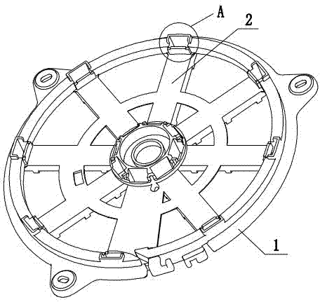
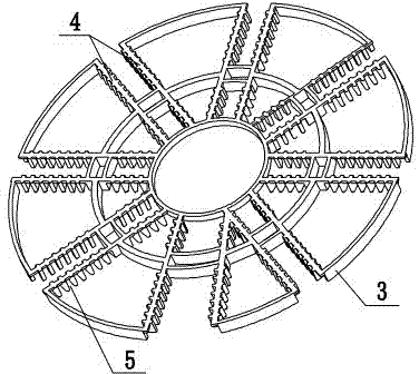
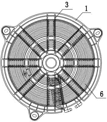
[0025] The wire reel of an induction cooker includes a wire reel base 1, a wire clamping frame 3, and a coil 6 arranged between the wire reel base 1 and the wire clamping frame 3. The coil 6 of the present invention is an aluminum wire; wherein, the wire reel base 1 is a planar structure, This simplifies the mold structure for making the wire reel base. A group of first reinforcing ribs 2 are evenly arranged on the wire reel base 1. The second reinforcing rib 4, on the second reinforcing rib 4, the clamping slots 5 for clamping the coil 6 are arranged at equal intervals, the clamping slot 5 is formed by two adjacent groove teeth, and the gap between the clamping slots 5 matches the diameter of the coil 6 The outer end of the first reinforcing rib 2 of the wire reel base 1 is provided with a boss 7 that matches the outer end structure of the second reinforcing rib 4 of the ...


PUM


Abstract

The invention relates to a wire coil, in particular to an induction cooker wire coil and a wire coil winding technology. The induction cooker wire coil is characterized in that a wire coil bottom base is of a plane structure, a wire clamping framework and the wire coil bottom base are respectively matched with corresponding strengthening ribs, the strengthening ribs on the wire clamping framework are provided with clamping grooves for clamping a coil at intervals, and the clamping grooves in the wire clamping framework are in clamping match with the wire coil bottom base after clamping the coil. When the wire coil is wound, a winding mould can be arranged on a winding machine first, the winding machine can be started, and the winding for the coil of which the shape is corresponding to the shape of the winding mould can be finished on the winding mould; then, the wire clamping framework can be clamped into the winding mould, an aluminum coil which is wound and formed on the winding mould can be clamped firmly through the wire clamping framework, and then the wire clamping framework clamping the coil firmly can be pushed out of the winding mould through a coil pushing-out groove arranged at the bottom part of the winding mould; and finally, the wire clamping framework clamping the coil firmly can be arranged in the wire coil bottom base. According to the induction cooker wire coil and the wire coil winding technology which are disclosed by the invention, on the premise without influencing the whole strength of the wire coil, a large amount of materials are saved, the winding technology is simplified, and the winding efficiency is increased.

Description

technical field [0001] The invention relates to a wire reel, in particular to an induction cooker wire reel and a wire reel winding process. Background technique [0002] The wire reel is the basic component of the induction cooker, and the structural design of the wire reel has always been the focus of product development for the induction cooker manufacturer. At present, laminated coils are gradually applied to induction cookers, leading to changes in the winding method of coils. The upper and lower coils are fixed by glue or the coils are positioned by clamping frames. Although these methods can position the laminated coil, the glue bonding process is not only complicated, but also consumes more chemical adhesives, which increases the cost, and the winding type is directly wound on the base of the wire reel, and the winding needs to be replaced repeatedly. The base of the wire reel increases the production process, and the clamping frame also participates in the winding ...

Claims


Application Information

Patent Timeline
Patent Type & Authority Patents(China)
IPC IPC(8): H05B6/36H01F41/06H01F27/30H01F41/098
Inventor 高新忠孙亮陆祥
Owner 杭州信多达电子科技有限公司
Learn More