Heat dissipation device using latent heat functional fluid and heat dissipation method thereof

A technology of functional fluid and heat dissipation device, applied in semiconductor devices, electric solid state devices, cooling/ventilation/heating transformation, etc., can solve the problems of difficulty in heat dissipation or increase in cost, and achieve the effect of extending heat dissipation time

Active Publication Date: 2012-07-04
HUAZHONG UNIV OF SCI & TECH
View PDF4 Cites 13 Cited by
  • Summary
  • Abstract
  • Description
  • Claims
  • Application Information

AI Technical Summary

Problems solved by technology

In this situation, the heat generation and heat dissipation of electronic devices are carried out simultaneously, which greatly increases the difficulty or cost of heat dissipation

Method used


Image

  • Heat dissipation device using latent heat functional fluid and heat dissipation method thereof
  • Heat dissipation device using latent heat functional fluid and heat dissipation method thereof
  • Heat dissipation device using latent heat functional fluid and heat dissipation method thereof

Examples


Embodiment 1

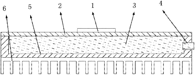
[0038] figure 1 It is a structural schematic diagram according to Embodiment 1 of the present invention, such as figure 1 As shown in , the heat dissipation device is composed of a discontinuous working heat source 1 , a cover plate 2 , a latent heat type functional fluid 3 , a liquid injection pipe 4 , and a housing 5 . The discontinuous working heat source 1 is arranged on the outer surface of the cover plate 2 or the housing 5 , and the discontinuous working heat source 1 is arranged on the outer surface of the cover plate 2 in this embodiment. The number of discontinuously working heat sources 1 can be one or more than two, and the number of heat sources 1 in this embodiment is one. The cover plate 2 is connected and closed with the housing 5 to form an inner chamber, and the latent heat functional fluid 3 is injected into the inner chamber through the liquid injection pipe 4 . The cover plate 2 can be a flat plate or have one or more protrusions protruding toward the in...

Embodiment 2

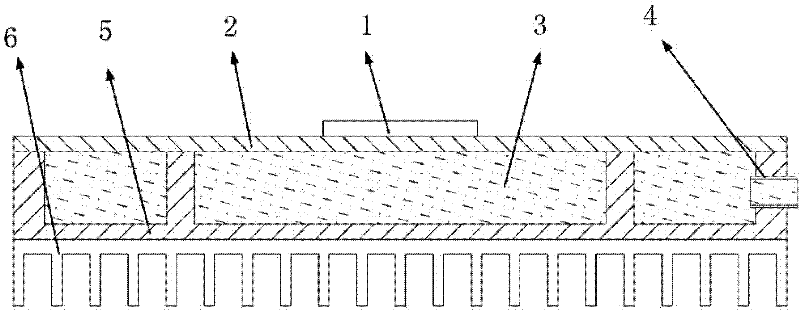
[0050] The difference between the second embodiment and the first embodiment is that in the second embodiment, there are pillars on the bottom surface of the casing 5 opposite to the cover plate. The pillars protrude toward the inner chamber and are connected with the cover plate. Improve the mechanical strength of the cooling device, see figure 2 .

Embodiment 3

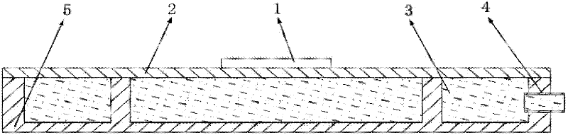
[0052] The difference between the third embodiment and the second embodiment is that heat dissipation without fins is realized in the embodiment. In Embodiment 3, the working time of the discontinuously working heat source 1 is relatively short, the non-working time is relatively long, the latent heat functional fluid 3 stores less heat, and the heat dissipation device dissipates heat for a long time through the heat dissipation area of ​​the cover plate 2 and the housing 5 It can meet the requirements of heat dissipation, without the need of heat dissipation fins 6, and realizes the technical effect of no fins. For details, see image 3 .


PUM


Abstract

The invention relates to a device for heat dissipation of an electronic apparatus with a discontinuous work heat source and a corresponding heat dissipation method. The device comprises a housing made of a heat conductive material; a cover plate made of a heat conductive material, connected with the housing and closed with the housing to from an inner chamber; a liquid injection tube for injecting a latent heat functional fluid; and a latent heat functional fluid filled in the inner chamber. The latent heat functional fluid stores the heat that is not discharged immediately inside when the discontinuous work heat source works and diffuses heat when the heat source stops working so as to realize non-synchronous operation of heat production and heat dissipation. Through the invention, partial storage and partial dissipation of heat are realized by phase change latent heat of the latent heat functional fluid. Heat stored is dissipated continuously when the heat source stops working, heat production and heat dissipation are carried out in a non-synchronous manner and the heat dissipation time is prolonged so as to obtain the technical effect of reducing the area of heat dissipation fins or even realizing fin free heat dissipation.

Description

technical field [0001] The invention relates to a heat dissipation device and a heat dissipation method of an electronic device, more particularly, to a heat dissipation device and a heat dissipation method for an electronic device with a discontinuous working heat source by using a latent heat type functional fluid. Background technique [0002] With the continuous development of electronic technology and packaging technology, electronic devices are highly integrated, the volume of components is becoming smaller and smaller, and the heat flux density is also increasing sharply. High heat flux puts forward higher heat dissipation requirements for electronic components. If the heat dissipation is not timely, the temperature of the electronic equipment will increase rapidly, leading to the failure or damage of the electronic equipment. Therefore, it is very important to realize effective heat dissipation for the electronic equipment. [0003] Commonly used heat dissipation me...

Claims


Application Information

Patent Timeline
Patent Type & Authority Applications(China)
IPC IPC(8): H05K7/20H01L23/427
Inventor 罗小兵付星胡锦炎刘胜
Owner HUAZHONG UNIV OF SCI & TECH
Why Eureka
Try Eureka