Nozzle arrangement

A nozzle device and nozzle technology, applied in the direction of spraying device, spraying device, liquid spraying device, etc., can solve the problems of increasing operating costs, etc., and achieve the effect of improving operation rate and improving versatility

Inactive Publication Date: 2012-07-04
EISENMANN CORP
View PDF7 Cites 4 Cited by
  • Summary
  • Abstract
  • Description
  • Claims
  • Application Information

AI Technical Summary

Problems solved by technology

This in turn increases the overall operating costs

Method used


Image

  • Nozzle arrangement
  • Nozzle arrangement
  • Nozzle arrangement

Examples


Embodiment Construction

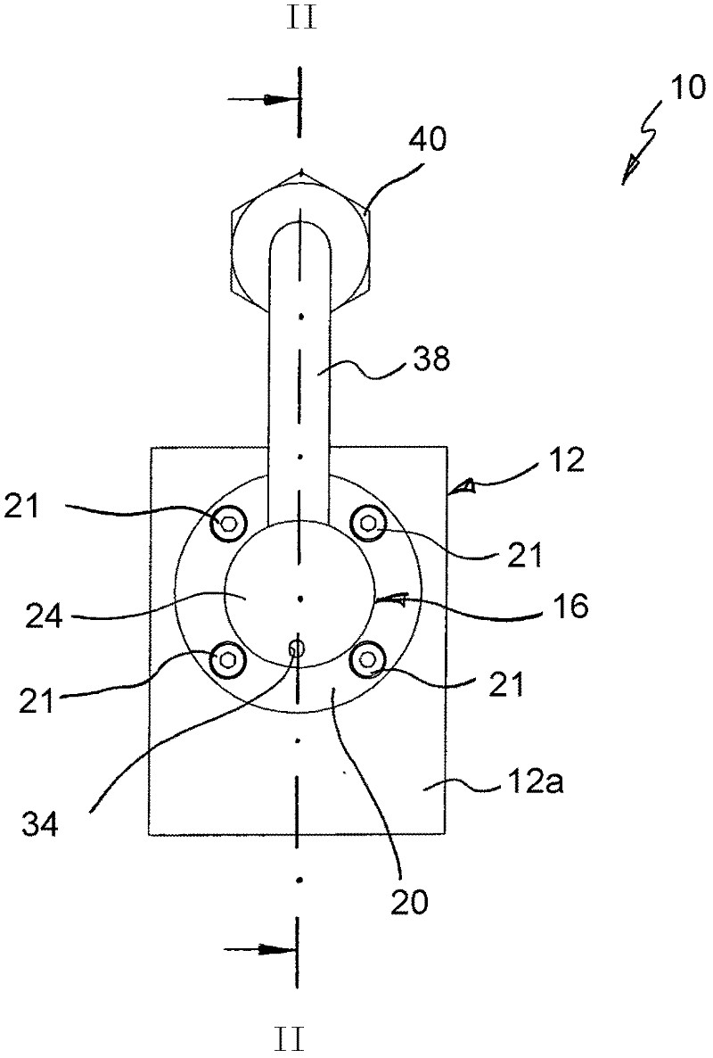
[0040] see first figure 1 with 2 , wherein 10 generally indicates a nozzle arrangement, by means of which anticorrosion wax can be sprayed into the cavity of the vehicle body.

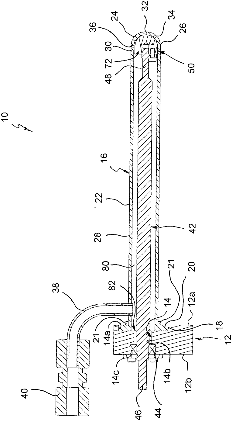
[0041] The nozzle arrangement 10 comprises a support block 12 having two opposite and mutually parallel outer surfaces 12a, 12b. A stepped through hole 14 passes through the support block 12 perpendicular to the outer surface. From the outer surface 12a to the outer surface 12b, the through hole 14 comprises three sections 14a, 14b, 14c each having a circular cross-section, but they have different diameters, wherein the section 14a has the largest diameter and the middle section 14b has the smallest diameter. Diameter, segment 14c has a diameter in between.

[0042] The nozzle assembly 10 also includes a cylindrical lance 16 . The lance 16 has at its axially open fixed end 18 a fixing flange 20 extending in the peripheral direction. The fixing flange 20 fits in the section 14 a of the through hole...


PUM


Abstract

A nozzle arrangement for applying coating material in cavities of objects, in particular of vehicle bodies, comprises a nozzle element (16; 116), which can be connected to a material source and comprises a first discharge opening (34; 134) and at least one further discharge opening (36; 136), by way of which coating material can be discharged. By means of a directing device (50; 150), the flow path of the coating material from the material source can be set in such a way that the flow path leads optionally to the first discharge opening (34; 134) and / or to the at least one further discharge opening (36; 136).

Description

technical field [0001] The invention relates to a nozzle device for applying a coating material in a cavity of an object, in particular a motor vehicle body, which has a nozzle element connectable to a material source, said nozzle element comprising a coating material through which the coating material can be delivered The first discharge port and at least one other discharge port. Background technique [0002] A nozzle arrangement of this type is known, for example, from US Pat. For this purpose, the nozzle element is usually designed as an elongated lance with a plurality of discharge openings at its free end. The spray gun is guided by means of the arm of the multi-axis painting robot and can be moved into the cavity of the vehicle body to be treated for painting, so that the area of ​​the spray gun with the outlet opening is located inside the cavity. Smearing can also be done manually in some cases. [0003] A car body has as many as 120 cavities, which can be very d...

Claims


Application Information

Patent Timeline
Patent Type & Authority Applications(China)
IPC IPC(8): B05B1/16B05B13/06B05B15/555
CPCB05B15/0258B05B7/262B05B13/0627B05B1/1636B05B13/0431B05B15/555
Inventor M·阿尔布雷克特F·汉姆舍尔
Owner EISENMANN CORP
Why Eureka
Try Eureka