Method and device for calcining materials

A material and calcination technology, applied in lime production and other directions, can solve the problems of affecting the quality of lime products, blocking gas circulation channels, and uneven heating of limestone, saving high-quality raw materials, reducing contact, and avoiding carbonation problems.

Active Publication Date: 2011-10-19
SHIJIAZHUANG XINHUA IND FURNACE CO LTD
View PDF6 Cites 16 Cited by
  • Summary
  • Abstract
  • Description
  • Claims
  • Application Information

AI Technical Summary

Problems solved by technology

The disadvantage of this process is: the stone in the shaft kiln moves from top to bottom, the furnace gas flows from bottom to top, the direction of furnace gas flow is opposite to the direction of stone flow, the gas resistance of stone is large, and the pressure in the furnace is high, which is prone to Gas segregation phenomenon causes uneven heating of limestone and affects product quality
However, this patented technology mixes fuel and limestone in the calcination chamber and burns directly to decompose the limestone. The burning dust and sulfur in the flue gas and other harmful substances directly adhere to the surface of the lime product, affecting the quality of the lime product.
After cooling the lime and preheating the limestone, the dust-containing gas enters the regenerator and accumulates between the regenerators, blocking the gas circulation channel and reducing the heat transfer efficiency, requiring frequent cleaning

Method used


Image

  • Method and device for calcining materials
  • Method and device for calcining materials
  • Method and device for calcining materials

Examples


Embodiment Construction

[0014] The present invention will be further described below in conjunction with the accompanying drawings.

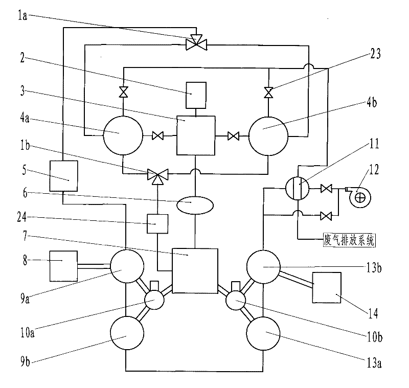
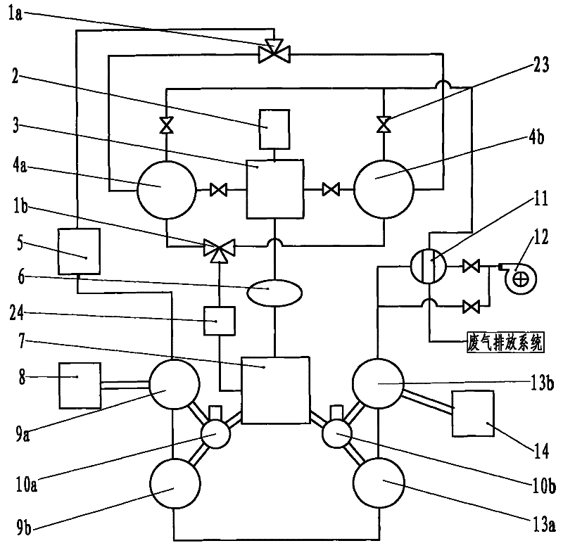
[0015] The device for calcining materials of the present invention is as figure 1 As shown, it includes: combustion chamber 3, preheating chamber (9a, 9b), calcining chamber 7, cooling chamber (13a, 13b), cyclone separator 5, heat exchanger 11, screw conveyor (10a, 10b), smoke Gas precipitator 24, regenerators (4a, 4b), feed equipment 8, discharge equipment 14 and exhaust gas discharge system. The device is a split structure of combustion chamber, preheating chamber, calcining chamber and cooling chamber. The preheating chamber 9a is a low temperature preheating chamber, the preheating chamber 9b is a high temperature preheating chamber, the cooling chamber 13a is a high temperature cooling chamber, and the cooling chamber 13b is a low temperature cooling chamber. The feed inlets of the preheating chamber, the calcining chamber and the cooling chamber are respectivel...


PUM


Abstract

The invention provides a method and a device for calcining materials. The device has a splitting type structure comprises a burning chamber, preheating chambers, a calcining chamber, cooling chambers, a heat accumulator, a gas processing unit, a material conveying machine, a feed device, a discharge device and an exhaust gas discharging system. Material to be calcined is conveyed by the material conveying machine between the preheating chambers, between the preheating chambers and the calcining chamber, between the calcining chamber and the cooling chamber and between the cooling chambers. Smoke generated by the burning in the external burning chamber is processed by the gas processing unit, and then enters the burning chamber for calcining the material. Air for cooling lime and preheating limestone material is subject to dust removing by a cyclone separator and is preheated by the heat accumulator, and then enters the burning chamber for supporting combustion. In the invention, the fuel burning and the material calcining are separated, so that the pollution of lime products caused by harmful substances can be avoided, and the quality of the lime product can be improved. The gas is subject to dust removing and then enters the heat accumulator, thus avoiding blocking a gas channel in the heat accumulator. The material conveying machine is used for conveying the material, so that the conveying efficiency is high, and the occupied space is small.

Description

Technical field: [0001] The invention belongs to the technical field of chemical production, relates to a method and a device for calcining materials, and in particular to the improvement of a split-type method and device for calcining materials. Background technique: [0002] In addition to being an important building material, lime is also an important raw material for metallurgy and chemical industries. The traditional technology is to use dolomite and limestone as raw materials, and use a shaft kiln with a burning beam to calcinate into lime. The disadvantage of this process is: the stone in the shaft kiln moves from top to bottom, the furnace gas flows from bottom to top, the direction of furnace gas flow is opposite to the direction of stone flow, the gas resistance of stone is large, and the pressure in the furnace is high, which is prone to Gas segregation phenomenon causes limestone to be heated unevenly and affects product quality. The applicant has disclosed a u...

Claims


Application Information

Patent Timeline
Patent Type & Authority Applications(China)
IPC IPC(8): C04B2/10C04B2/12
CPCY02P40/40
Inventor 贾会平
Owner SHIJIAZHUANG XINHUA IND FURNACE CO LTD
Why Eureka
Try Eureka