Protection circuit for power amplifier

A technology for power amplifiers and protection circuits, which is applied in the layout of amplifier protection circuits, power amplifiers, amplifiers, etc.

Inactive Publication Date: 2012-07-04
QUALCOMM INC
View PDF3 Cites 9 Cited by
  • Summary
  • Abstract
  • Description
  • Claims
  • Application Information

AI Technical Summary

Problems solved by technology

The load impedance can vary due to various disturbances and can cause the power amplifier to observe high peak voltages
The high peak voltage may exceed a level that ensures reliable operation of the power amplifier

Method used


Image

  • Protection circuit for power amplifier
  • Protection circuit for power amplifier
  • Protection circuit for power amplifier

Examples


Embodiment Construction

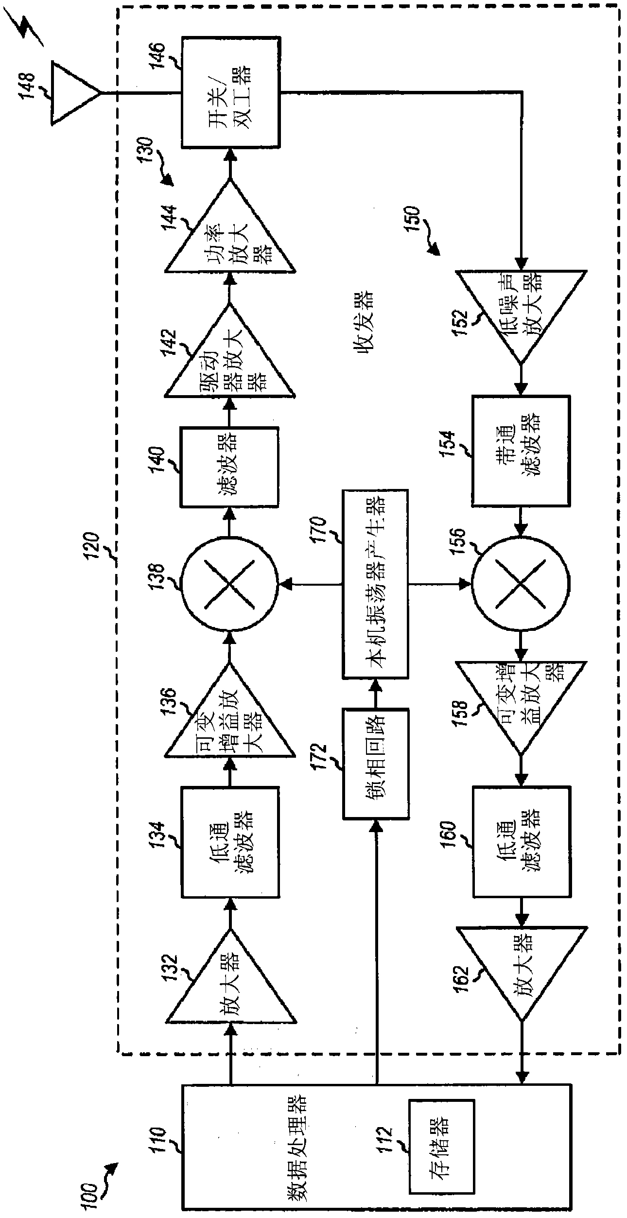
[0013] The detailed description set forth below is intended as a description of exemplary designs of the invention and is not intended to represent the only designs with which the invention may be practiced. The term "exemplary" is used herein to mean "serving as an example, instance, or illustration." Any design described herein as "exemplary" should not necessarily be construed as preferred or advantageous over other designs. The detailed description includes specific details for the purpose of providing a thorough understanding of the exemplary design of the invention. It will be apparent to those skilled in the art that the exemplary designs described herein may be practiced without these specific details. In some instances, well-known structures and devices are shown in block diagram form in order to avoid obscuring the novelty of the exemplary designs presented herein.

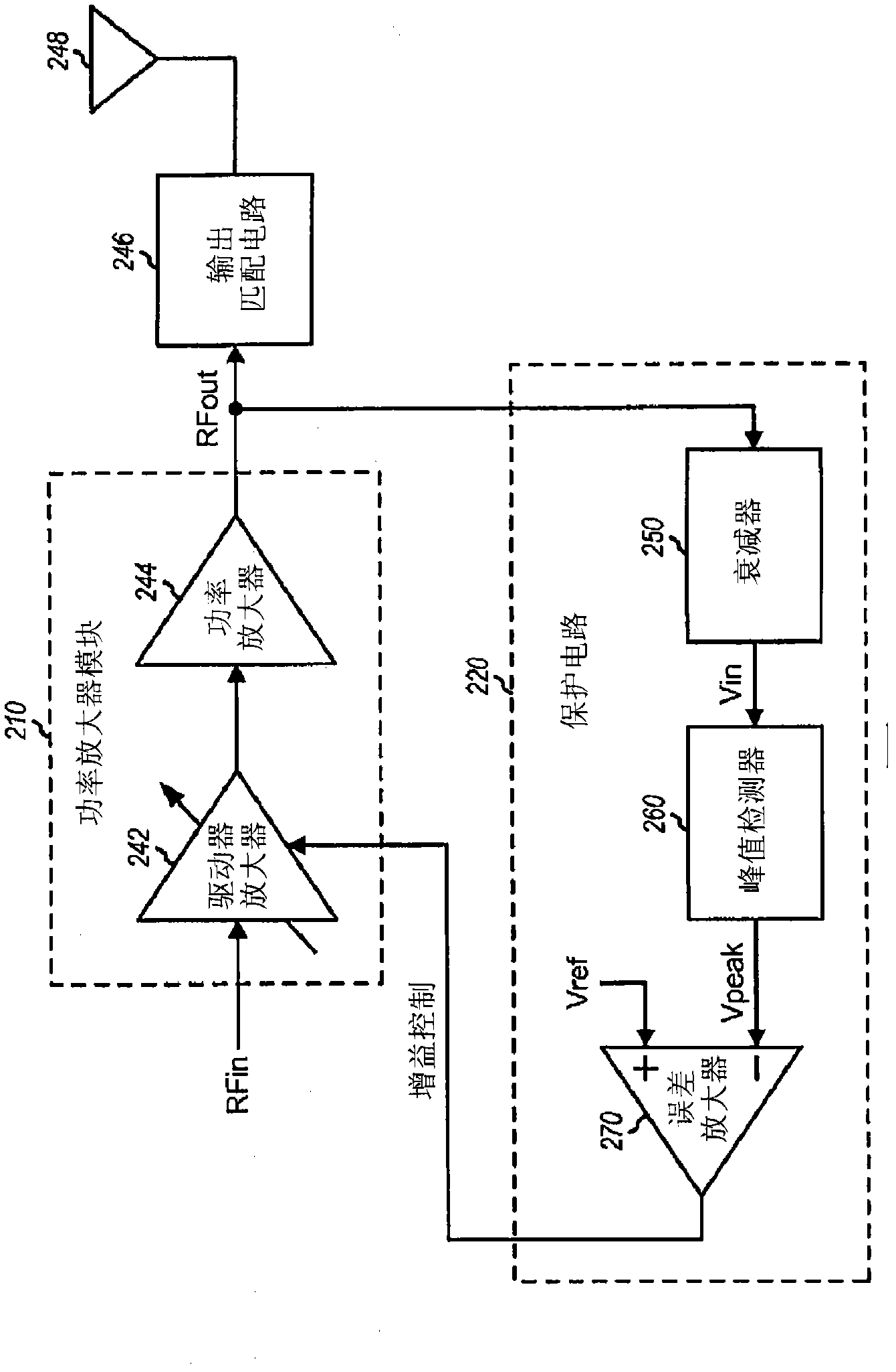
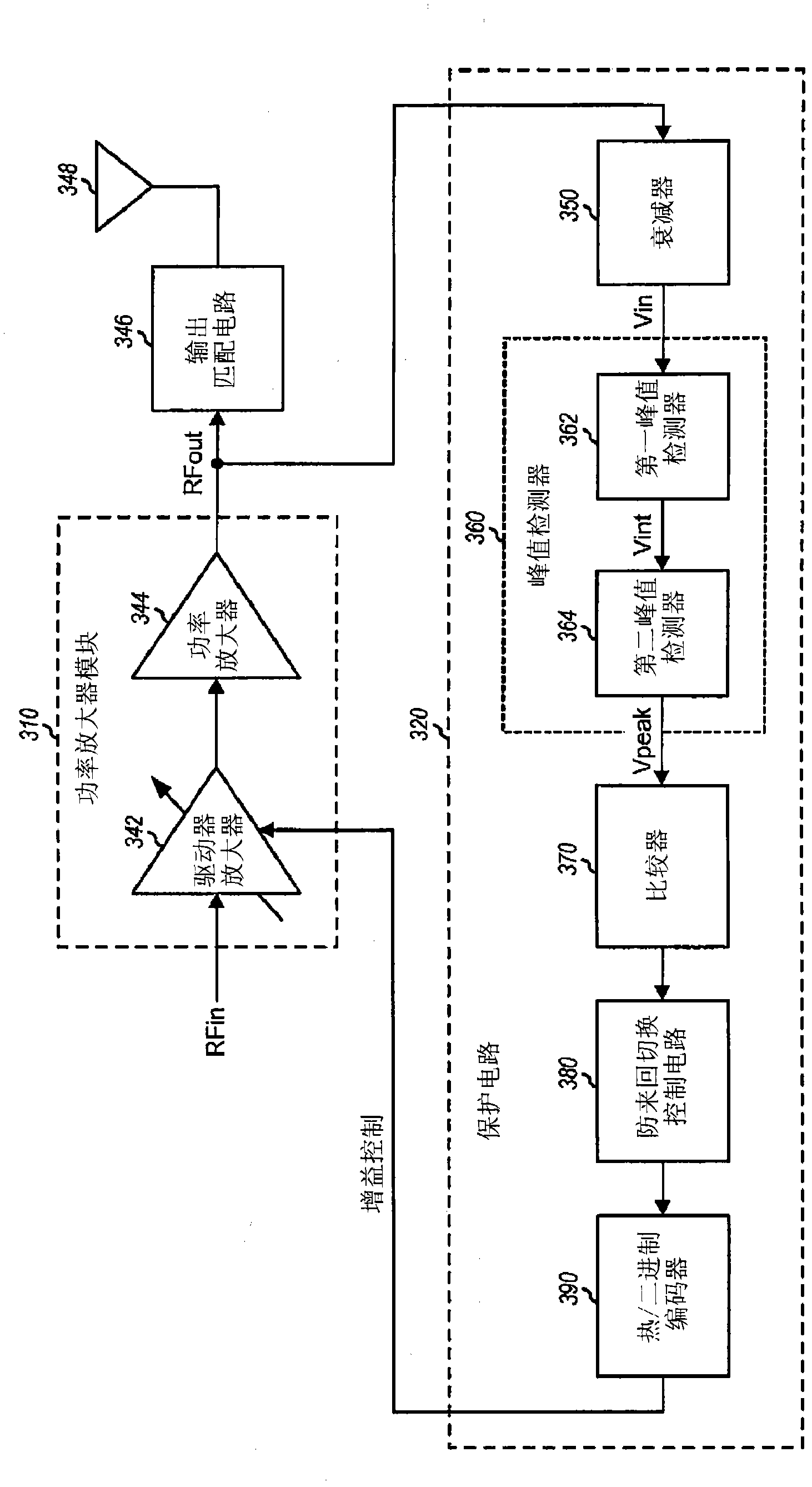
[0014] This article describes techniques for protecting power amplifiers from high peak voltages. ...


PUM


Abstract

Techniques for protecting a power amplifier (PA) are described. In an exemplary design, an apparatus includes a PA module (310) to amplify an input RF signal and provide an output RF signal and a protection circuit (320) to control a transmitter gain to protect the PA module against high peak voltage. In an exemplary design, the protection circuit (329) includes a set of comparators (370) to quantize an analog input signal and provide digital comparator output signals used to adjust the transmitter gain. In another exemplary design, the protection circuit reduces and increases the transmitter gain with hysteresis. In yet another exemplary design, the protection circuit has faster response to rising amplitude than falling amplitude of the output RF signal. The hysteresis and / or the different rise and fall responses may allow the protection circuit to avoid toggling the transmitter gain under severe load mismatch and to handle time-varying envelope due to amplitude modulation.

Description

[0001] Claiming priority under 35 U.S.C. §119 [0002] This patent application claims priority to U.S. Provisional Application No. 61 / 235,313, filed August 19, 2009, entitled "VSWR PROTECTION FOR POWER AMPLIFIERS," assigned to present assignee, and is expressly incorporated herein by reference. technical field [0003] The present invention relates generally to electronic equipment, and more particularly to protection circuits for power amplifiers. Background technique [0004] Wireless communication devices typically include a transmitter that supports data transmission. The transmitter typically includes a power amplifier that amplifies radio frequency (RF) signals and provides high output power. The power amplifier can be designed to drive a specific load impedance (eg, 50 ohms). The load impedance can vary due to various disturbances and can cause high peak voltages to be observed by the power amplifier. The high peak voltage may exceed a level that ensures reliable...

Claims


Application Information

Patent Timeline
Patent Type & Authority Applications(China)
IPC IPC(8): H03F1/52H03F3/24H03G3/30G01R19/04H04W52/08
CPCH03G3/3042H03F2200/435H03F1/52H03F3/24H03F2200/78H04B2001/0408
Inventor 文俊・苏阿里斯托泰莱・哈奇克里斯托斯居尔卡瓦・S・萨霍塔马尔科・卡西亚
Owner QUALCOMM INC
Why Eureka
Try Eureka