
Ventilating and filtering device capable of automatically dedusting and dedusting method

A filter device and automatic dust removal technology, applied in separation methods, dispersed particle filtration, chemical instruments and methods, etc., can solve the problems of poor dust separation effect, poor electrostatic dust removal effect, and complete removal of unfavorable dust.

Active Publication Date: 2012-07-11
CHINA MOBILE GROUP ANHUI
View PDF6 Cites 14 Cited by
  • Summary
  • Abstract
  • Description
  • Claims
  • Application Information

AI Technical Summary

Problems solved by technology

Although these ventilation and energy-saving systems have a certain dust removal function, there are some problems. For example, the ventilation and energy-saving systems that use water spray for dust removal are not suitable for communication equipment rooms, because water droplets will enter the equipment room with the air during water spraying. Cause adverse effects, while the effect of electrostatic dust removal is poor, the cost is high, and it is not conducive to energy saving
Centrifugal force dust removal uses the centrifugal force of dust to achieve air classification, and the separation effect on small dust is not good.
Using a brush to remove dust is likely to cause dust to scatter, and it is easy to form secondary dust collection, which is not conducive to the complete removal of dust

Method used


Image

  • Ventilating and filtering device capable of automatically dedusting and dedusting method
  • Ventilating and filtering device capable of automatically dedusting and dedusting method
  • Ventilating and filtering device capable of automatically dedusting and dedusting method

Examples


Embodiment Construction

[0016] The content of the present invention will be further described in detail below in conjunction with specific embodiments, but it should be understood that the following specific description does not constitute any limitation on the protection scope of the present invention.

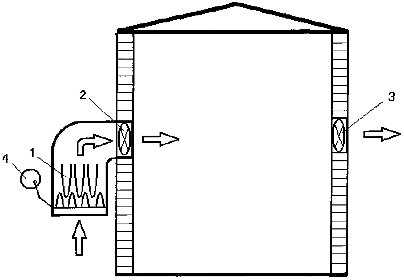
[0017] figure 1 Disclosed is a working schematic diagram of an automatic dust removal ventilation filter device for a computer room according to the present invention. The filter device includes a bag-type air filter 1 , an air intake fan 2 , an exhaust fan 3 , and an automatic dust removal vibration device 4 . In addition, in order to realize the automatic control function, the present invention may also include a controller (not shown) and the like.

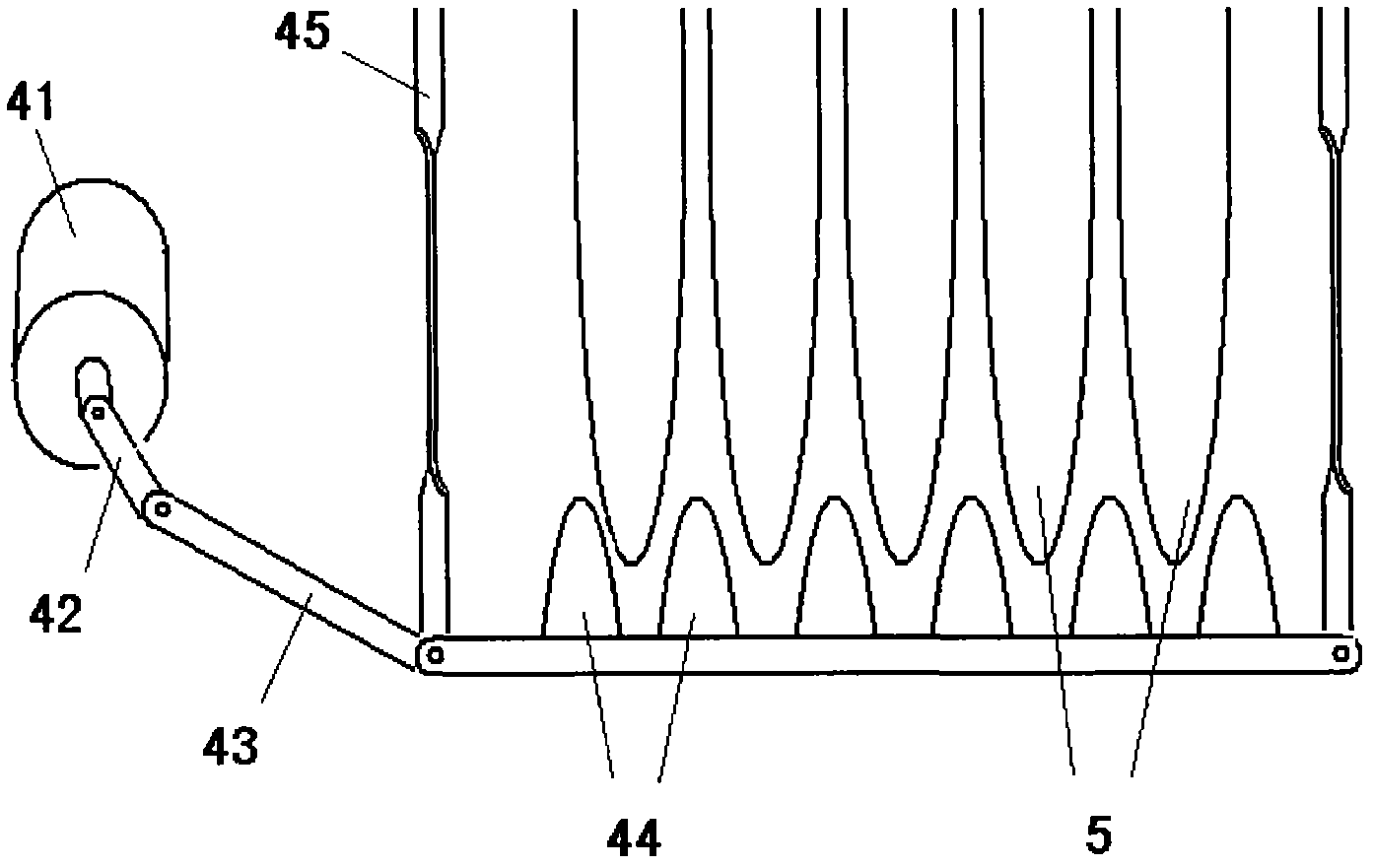
[0018] figure 2 A schematic structural diagram of the automatic dust removal vibration device is shown, including a dust removal motor 41, a crank 42, a connecting rod 43, a vibration grid 44, a controller, a sensor, etc. (not shown). The crank co...


PUM


Abstract

The invention relates to a ventilating and filtering device capable of automatically dedusting. The device comprises a bag type air filter and an automatic dedusting vibrator for driving the bag type air filter to vibrate, wherein a crank connecting rod mechanism consisting of the dedusting motor, the crank and the connecting rod of the automatic dedusting vibrator is hinged with a vibrating grate; the vibrating grate is flexibly connected with a filter bag support frame body by an elastic pull rod. According to the invention, the dedusting motor runs, circular motion is converted into reciprocating motion through the crank connecting rod mechanism to drive the vibrating grate to vibrate; a filter bag is clamped in the grates of the vibrating grate and vibrates along with the grates, so that the aim of dedusting is achieved. According to the invention, the circular motion of the motor is converted into the reciprocating motion through the crank connecting rod mechanism and is transmitted to the bag type filter through the vibrating grate, so that the vibrating grate is vibrated; the vibration mode has the advantages of large vibration amplitude, strong dynamics and the like; and the vibration mode is matched with the filter bag type air filter, so that the filtering effect and the dedusting effect can be effectively improved.

Description

technical field [0001] The invention relates to the technical field of air conditioners, in particular to the technical field of automatic dust removal for air conditioners. Background technique [0002] Ventilation energy-saving technology is to directly introduce cold air from the outside into the computer room to cool down the communication equipment. Among various energy-saving technologies, it is an energy-saving method with the greatest energy-saving potential. At present, ventilation and energy-saving technology has attracted great attention from the communication industry. [0003] Existing ventilation and energy-saving technologies are generally composed of air inlet unit, air outlet unit, central control unit, air dust filter device, air conditioning control device and other installation accessories. The working process is: when the temperature in the machine room is higher than the set temperature, The system automatically detects the outdoor temperature and humi...

Claims


Application Information

Patent Timeline
IPC IPC(8): B01D46/04B01D46/42
Inventor 李长云
Owner CHINA MOBILE GROUP ANHUI
Learn More