Control circuit for emergency brake loop

A technology of emergency braking and loop control, applied to locomotives and other directions

Active Publication Date: 2012-07-11
TRAFFIC CONTROL TECH CO LTD
View PDF5 Cites 3 Cited by
  • Summary
  • Abstract
  • Description
  • Claims
  • Application Information

AI Technical Summary

Problems solved by technology

[0014] The technical problem to be solved by the present invention is: how to make the two hosts output the same signal, and at the same time ensure that when one of the two hosts fails to work, the system can operate normally without using a cutting device

Method used


Image

  • Control circuit for emergency brake loop
  • Control circuit for emergency brake loop
  • Control circuit for emergency brake loop

Examples


Embodiment 1

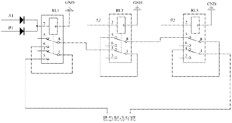
[0029] figure 2 It is a structural schematic diagram of the emergency braking loop control circuit according to the first embodiment of the present invention; refer to figure 2 , the emergency braking loop control circuit of this embodiment includes: a dynamic closing relay (that is, "RL1" in the figure) and two dynamic breaking relays (that is, respectively in the figure) connected in series in the emergency braking loop "RL2" and "RL3"), the moving-on relay is simultaneously controlled by two hosts, and the two moving-off relays are respectively controlled by two hosts (not shown, the output signal of which is "A2" in the figure " and "B2") control, one end of the two control ends of the moving-close relay is connected to the power supply, and the other end is connected to the two hosts (not shown, the output signals of which are "A1" and "B1") are respectively connected, a diode is provided between the two hosts and the moving-closing relay, and the cathode of the diode ...

Embodiment 2

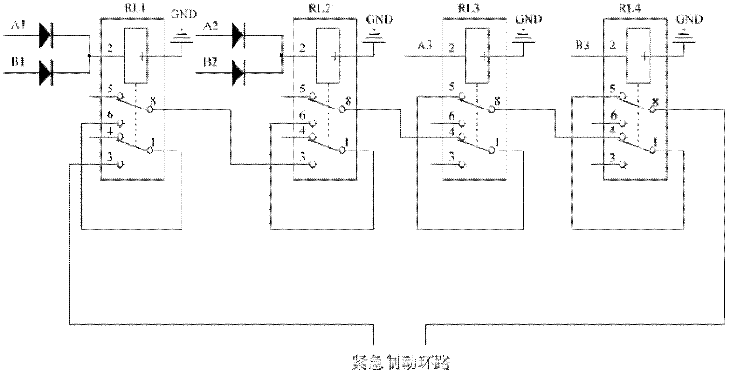
[0032] image 3 It is a structural schematic diagram of the emergency braking loop control circuit according to the second embodiment of the present invention; refer to image 3 , the emergency braking loop control circuit of this embodiment includes: two active closing relays (ie respectively "RL1" and "RL2" in the figure) connected in series in the emergency braking loop and two active breaking relays Relays (that is, respectively "RL3" and "RL4" in the figure), the two moving relays are simultaneously controlled by two hosts (not shown, whose output signals are "A3" and "B3" in the figure) control, the two active-off relays are respectively controlled by two hosts, one end of the two control ends of each active-on relay is connected to the power supply, and the other end is connected to the two hosts (not shown, its The output signals are "A1", "B1", "A2" and "B2" in the figure, where "A1" and "A2" are sent by the same host, and "B1" and "B2" are sent by the same host) are...


PUM


Abstract

The invention discloses a control circuit for an emergency brake loop, relating to the technical field of train control. The control circuit comprises at least one normally opening relay and two normally closed relays, which are connected in series in an emergency brake loop, wherein the at least one normally opening relay is simultaneously controlled by two host machines, and the two normally closed relays are respectively controlled by the two host machines. According to the control circuit for the emergency brake loop, the normally opening relay controlled simultaneously by the two host machines is arranged in series in the emergency brake loop, so that the two host machines output same signals, and the system can normally operate without using a switch device after one of the two host machines cannot work.

Description

technical field [0001] The invention relates to the technical field of train control, in particular to an emergency braking loop control circuit. Background technique [0002] In the field of computer control, it is very common to use dual machines for control, also known as dual machine hot standby. Dual-machine hot standby uses two hosts to back up each other and perform the same operation together. When a host fails, another host can take over the operation tasks, so that the system can automatically ensure continuous operation without manual intervention. [0003] According to the switching mode in the work, the dual-machine hot standby is divided into: active-standby mode (Active-Standby mode) and dual-host mode (Active-Active). [0004] Active-standby mode (Active-Standby mode) means that server data including database data is written to two or more servers at the same time, or a shared storage device is used. When the active server fails, the standby machine is act...

Claims


Application Information

Patent Timeline
Patent Type & Authority Applications(China)
IPC IPC(8): B61C17/00
Inventor 陈寅昊李超
Owner TRAFFIC CONTROL TECH CO LTD
Why Eureka
Try Eureka