Improved hydrolytic acidification tank

A technology for hydrolysis and acidification tank and water inflow, applied in the field of sewage treatment and environmental protection, can solve the problems of reducing the effective contact between activated sludge and sewage, reducing the effect of pollutant removal, lack of sludge return system, etc., and achieving complete hydrolysis and acidification. , the effect of high activated sludge concentration, sludge concentration and high activity

Active Publication Date: 2013-04-10
江苏凌志市政工程设计研究院有限公司 +3
View PDF1 Cites 0 Cited by
  • Summary
  • Abstract
  • Description
  • Claims
  • Application Information

AI Technical Summary

Problems solved by technology

However, this method lacks a sludge return system, which reduces the effective contact between activated sludge and sewage. At the same time, the setting of multi-circulation treatment pools (three or more) makes more reaction areas in static sedimentation or unconnected, reducing the The reaction residence time is reduced, resulting in a reduction in the removal of pollutants

Method used


Image

  • Improved hydrolytic acidification tank
  • Improved hydrolytic acidification tank

Examples


Embodiment 1

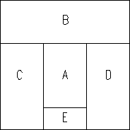
[0018] Example 1, the improved hydrolysis acidification tank, the influent mixing zone A, the sludge return and the discharge zone E are arranged up and down to connect with the sludge return device, and a sequence of batch processing zones C and D are respectively set on both sides. The sequence batch treatment area alternates with the second stirring reaction area and the static sedimentation area; the first stirring reaction area B is set at the horizontal end of the water inlet mixing area A, sequence batch processing area C, and D, and the first stirring reaction area B They are respectively connected to the water inlet mixing area A, the two-sequence batch processing area C, and D; the two-sequence batch processing areas C and D are equipped with a stirring device, a water outlet device and a mud outlet device, and the mud outlet device is connected to the sludge return flow with discharge zone E.

[0019] There is a stirring device in the water inlet mixing area A, and ...

Embodiment 2

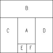
[0023] Example 2, with reference to Example 1, two side-by-side sludge return and discharge areas E and F are arranged below the influent mixing area A, which are respectively connected with the mud outlets of the adjacent sequence batch processing areas C and D. Sludge return and discharge areas E and F are equipped with sludge return devices connected to the water inlet mixing area A, and also have their own sludge discharge pipes.

[0024]The first period: Turn on the stirring device in the water inlet mixing zone A, the first stirring reaction zone B, the sludge return and discharge zone E, and the water outlet device in the sequence batch treatment zone C, and close the sequence batch treatment zone C The stirring device and the sludge return device in the sludge return and discharge area F allow the sewage to enter the water inlet mixing area A, fully mix with the returned activated sludge and enter the first stirring reaction area B for hydrolysis and acidification react...


PUM


Abstract

The invention discloses an improved hydrolytic acidification tank, which belongs to the technical field of sewage treatment and environment protection and relates to the improvement on hydrolytic acidification tanks in sewage treatment. The improved hydrolytic acidification tank comprises a water inflow mixing area, a stirring reaction area, two sequential batch treatment areas and a sludge backflow and discharge area. The whole hydrolytic acidification process is divided into five basic operation processes of water inflow mixing and stirring reaction, static precipitation, sludge and water separation, sludge backflow and water outflow, the five processes are respectively finished in five functional areas at the same time, and continuous hydrolysis can be realized by continuous water inflow and outflow. By the improved hydrolytic acidification tank, a precipitation tank can be removed, the sludge backflow can be realized, high concentration of activated sludge in a reaction tank can be kept, sludge can be fully contacted with wastewater, and a hydrolytic acidification effect can be fully exerted; and floor space and investment cost can be greatly reduced, and a process can be conveniently and flexibly operated and managed.

Description

technical field [0001] The invention belongs to the technical field of sewage treatment and environmental protection, and is an improvement to the hydrolysis and acidification tank in sewage treatment, and specifically relates to a method that can omit the sedimentation tank to realize sludge reflux, mixing and stirring reaction with influent water, static precipitation, mud-water separation, and sludge dehydration. Backflow and effluent are the hydrolytic acidification tanks in the basic operation process. Background technique [0002] The traditional sewage treatment process generally uses the primary sedimentation tank as a pretreatment system to remove suspended solids and particulate matter in the sewage, improve the biodegradability of the sewage and reduce the organic load of the subsequent treatment process, but the primary sedimentation tank mainly relies on physical action Pretreatment of sewage cannot improve the biodegradability of sewage, and the effluent still ...

Claims


Application Information

Patent Timeline
Patent Type & Authority Patents(China)
IPC IPC(8): C02F3/28
Inventor 汪文丽刘会平杨天龙张传可
Owner 江苏凌志市政工程设计研究院有限公司
Why Eureka
Try Eureka