Electrically controlled manipulation method of grader

A leveling, electromechanical technology, applied in the direction of mechanically driven excavators/dredgers, etc., can solve the problems of low transmission efficiency, low service life, inconvenient installation, etc., to achieve convenient system installation, long service life, and easy replacement and maintenance. Effect

Active Publication Date: 2012-07-11
SHANXI GUOLI INFORMATION TECH
View PDF4 Cites 3 Cited by
  • Summary
  • Abstract
  • Description
  • Claims
  • Application Information

AI Technical Summary

Problems solved by technology

[0007] The purpose of the present invention is to provide an electric control method for motor graders to solve the technical problems of inconvenient installation, low transmission efficiency, low service life, high operating noise and low reliability caused by the existing loader drive system

Method used


Image

  • Electrically controlled manipulation method of grader
  • Electrically controlled manipulation method of grader
  • Electrically controlled manipulation method of grader

Examples


Embodiment 1

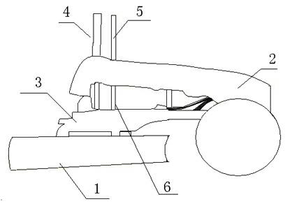
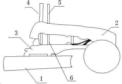
[0021] Such as figure 1 As shown, it at least includes the flat bucket 1 of the loader, the leveling body 2, the operating mechanism 15 and the operating mechanism 15. The flat bucket 1 is connected to the leveling body 2 through the leveling arm 3. The leveling arm 3 includes left and right arms, distributed At the left and right positions of the leveling body 2, movable joints are arranged on the left and right arms, and the left and right arms are respectively connected with electric cylinders 9 telescopic arm push rods 7, and the electric cylinders 9 cylinder bodies are fixed with the leveling body 2, left and right The electric cylinder 9 of the electric cylinder 9 is electrically connected with the operating mechanism 15 respectively, and the electric cylinder 9 of the left and right arms is controlled by the operating mechanism 15.

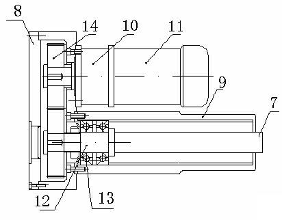
[0022] Such as figure 2 As shown, the electric cylinder 9 includes a motor 11, a gear pair 14, a gearbox 8, a transmission shaft 12, a t...

Embodiment 2

[0025] Electric cylinder 9 comprises motor 11, transmission shaft 12, transmission bearing 13 and push rod 7, and motor 11, transmission shaft 12, transmission bearing 13 and push rod 7 are on an axis, and motor 11 drives transmission shaft 12 to rotate through speed changer, transmission shaft 12 is fixed in the transmission bearing 13, and the push rod 7 extends or retracts with the rotation of the motor 11 shaft. When working, the electric cylinder 9 is connected with the operating mechanism 15 of the leveling body 2, and the push rod 7 is controlled to start and stop by the operating mechanism 15 , extend and retract, so that the leveling arm drives the leveling bucket to lift.

[0026] In the present invention, the electric cylinder 9 includes a left electric cylinder 4 and a right electric cylinder 5, and the left electric cylinder 4 and the right electric cylinder 5 are respectively on the left and right arms.

[0027] A complete electric cylinder should include a power...


PUM


Abstract

The invention relates to a loader, in particular to an electrically controlled manipulation method of a grader, which at least comprises a flat bucket, a grader body, an operating mechanism and a lifting mechanism of the loader, wherein the flat bucket is connected with the grader body through a ground arm; the ground arm comprises a left arm and a right arm; and the left arm and the right arm are provided with movable joints. The method is characterized in that the left arm and the right arm are respectively connected with a telescopic arm of an electric cylinder, the electric cylinders are fixed at the grader body and are electrically connected with the operating mechanism, the operating mechanism controls the electric cylinders of the left arm and the right arm, and a push rod of a telescopic electric cylinder drives the flat bucket to lift up and down and turn over. The invention provides an electrically controlled manipulation method of the grader, so as to solve the technical problems of inconvenient installation, low transmission efficiency, a short service life, large running noises and low reliability of the existing loader driving system.

Description

technical field [0001] The invention relates to a loader, in particular to an electric control method for a grader. Background technique [0002] The leveling bucket of the grader is connected with the leveling body through the leveling arm. The leveling arm is composed of left and right arms. There are movable joints on the left and right arms. The left and right arms are respectively connected with oil cylinder mechanisms. Telescoping makes the flat bucket lift, drop and flip the flat bucket. [0003] But the existing hydraulic system has the following problems: [0004] 1. The connection of the hydraulic pipeline is complex and prone to oil leakage and the installation of the system is inconvenient. [0005] 2. The efficiency of hydraulic transmission is low, so battery forklifts generally use a separate motor to drive the hydraulic pump. Due to the working principle and manufacturing process of the hydraulic pump, the working efficiency of the system is low, resulting...

Claims


Application Information

Patent Timeline
Patent Type & Authority Applications(China)
IPC IPC(8): E02F3/76E02F3/84
Inventor 曾卫东潘亚敏
Owner SHANXI GUOLI INFORMATION TECH
Why Eureka
Try Eureka