Underground floating valve with high-temperature resistance, high-pressure resistance and corrosion resistance

A corrosion-resistant and high-temperature-resistant technology, applied in wellbore/well valve devices, wellbore/well parts, earthwork drilling and production, etc., can solve problems such as high bottomhole temperature, high bottomhole pressure, and downhole accidents, and achieve The effects of increasing working life, preventing overvoltage damage, and stabilizing performance

Active Publication Date: 2012-07-11
CHINA UNIV OF PETROLEUM (EAST CHINA)
View PDF8 Cites 9 Cited by
  • Summary
  • Abstract
  • Description
  • Claims
  • Application Information

AI Technical Summary

Problems solved by technology

[0003] However, with the depletion of oil and gas resources in shallow formations and the deepening of the development of deep formation resources, the downhole blowout prevention tool-drilling tool float valve is facing new problems, that is, high bottomhole temperature and high bottomhole pressure in deep formations. It also contains hydrogen sulfide, and the complex downhole conditions affect the performance of some parts of the drilling tool float valve, resulting in the failure of the conventional float valve to work normally, and even causing downhole accidents
In addition, the stability of the drilling tool float valve is not very high, and the effective working time is also difficult to determine
Due to the deep wells drilled for the development of deep oil and gas resources, once downhole tools fail or downhole accidents occur, it takes a long time to deal with them, which increases the risk of drilling operations and affects the progress of oil and gas resources development.

Method used


Image

  • Underground floating valve with high-temperature resistance, high-pressure resistance and corrosion resistance
  • Underground floating valve with high-temperature resistance, high-pressure resistance and corrosion resistance
  • Underground floating valve with high-temperature resistance, high-pressure resistance and corrosion resistance

Examples


Embodiment Construction

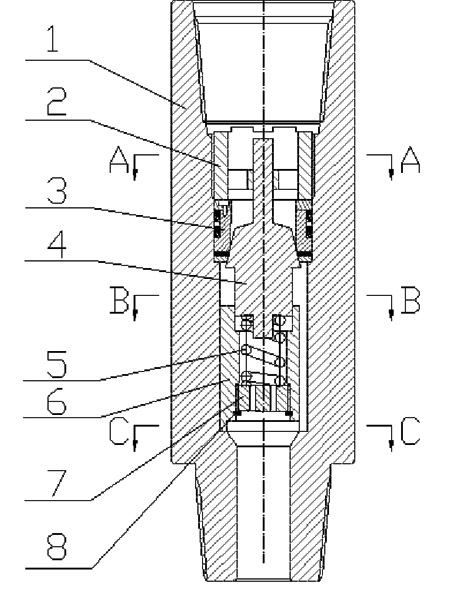
[0021] combined with Figure 1-4 , to further describe the present invention:

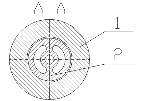
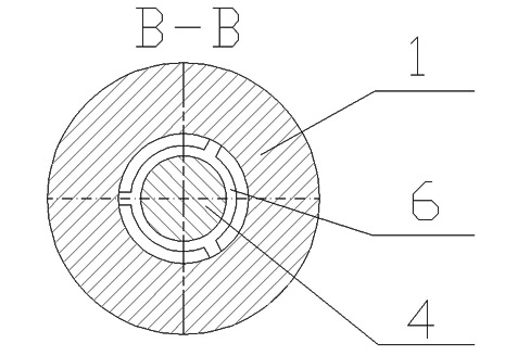
[0022] The present invention consists of a valve body 1, a valve core sleeve 2, a sealing assembly 3, a valve core 4, a spring 5, a valve seat 6, a spring plug 7, and a plug positioning ring 8. The valve core sleeve 2, The sealing assembly 3 and the valve seat 6 are assembled inside the valve body 1; the spring plug 7 and the plug positioning ring 8 are installed on the valve seat 6; the return spring 5 is located between the valve core 4 and the spring plug 7; The upper shaft of the valve core 4 is installed in the valve core pressure sleeve 2 , the taper surface is in contact with the sealing assembly 3 , the lower shaft is installed in the inner cavity of the valve seat 6 , and the bottom surface is in contact with the return spring 5 .

[0023] The valve body 1 is the mother body of the entire float valve, and other accessories are installed in the valve body 1; the upper and lower parts o...


PUM


Abstract

The invention relates to an underground floating valve with high-temperature resistance, high-pressure resistance and corrosion resistance. According to the technical scheme, the underground floating valve mainly comprises a valve body, a valve core pressing sleeve, a seal assembly, a valve core, a spring, a valve seat, a spring wire plug and a wire plug positioning ring, wherein the valve core pressing sleeve, the seal assembly and the valve seat are assembled inside the valve body; the spring wire plug and the wire plug positioning ring are arranged on the valve seat; a return spring is positioned between the valve core and the spring wire plug; an upper shaft of the valve core is arranged in the valve core pressing sleeve; a conical surface is in contact fit with the seal assembly; a lower shaft is arranged in an inner cavity of the valve seat; and a bottom surface is contacted with the return spring. The invention has the advantages that: the service life of a tool can reach more than 100 hours under the working condition that an operating temperature is not less than 180 DEG C and resisted pressure is not less than 150Mpa, so that the requirements of preventing underground internal blowout and ensuring the normal operation of an underground instrument in the process of developing oil and gas resources in a deep formation are met.

Description

technical field [0001] The invention relates to the field of oil and natural gas drilling engineering, in particular to an underground float valve resistant to high temperature, high pressure and corrosion. Background technique [0002] During the drilling process of oil and gas exploration and development, when the formation pressure is greater than the pressure of the drilling fluid column, the formation fluid may enter the drill string, resulting in the following types of problems and accidents: ①. Very fine, there will be a lot of fine sand in the annulus of the wellbore, and the mud will flow back when drilling and connecting a single root, a large amount of sand enters the drilling tool from the water hole of the drill bit, and the water hole may be blocked when the pump is turned on; ②Drilling When MWD and downhole power drilling tools are used in the middle, the flow channel of the tool itself is small. During the running process, cuttings and sand on the well wa...

Claims


Application Information

Patent Timeline
Patent Type & Authority Applications(China)
IPC IPC(8): E21B34/08
Inventor 管志川刘永旺许玉强玄令超张洪宁史玉才廖华林
Owner CHINA UNIV OF PETROLEUM (EAST CHINA)
Why Eureka
Try Eureka