Diaphragm compressed valve-less micropump

A compression-type, micro-pump technology, applied in the direction of pumps, pump components, variable-capacity pump components, etc., can solve the problems of high driving voltage and complex processing technology, and achieve the effects of prolonging service life, easy processing, and convenient control

Inactive Publication Date: 2012-07-11
TAIYUAN UNIV OF TECH
View PDF2 Cites 8 Cited by
  • Summary
  • Abstract
  • Description
  • Claims
  • Application Information

AI Technical Summary

Problems solved by technology

[0003] The purpose of a thin-film compression valveless micropump of the present invention is to overcome the disadvantages of high driving voltage and complicated processing technology of the existing valveless micropump, and provide a micro vibrating motor-driven micropump that can work at a low voltage of 3V. valve micropump to reduce the driving voltage of the micropump and improve the working stability of the micropump

Method used


Image

  • Diaphragm compressed valve-less micropump
  • Diaphragm compressed valve-less micropump
  • Diaphragm compressed valve-less micropump

Examples


Embodiment approach 1

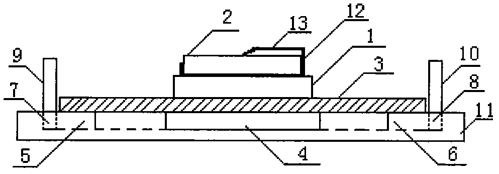
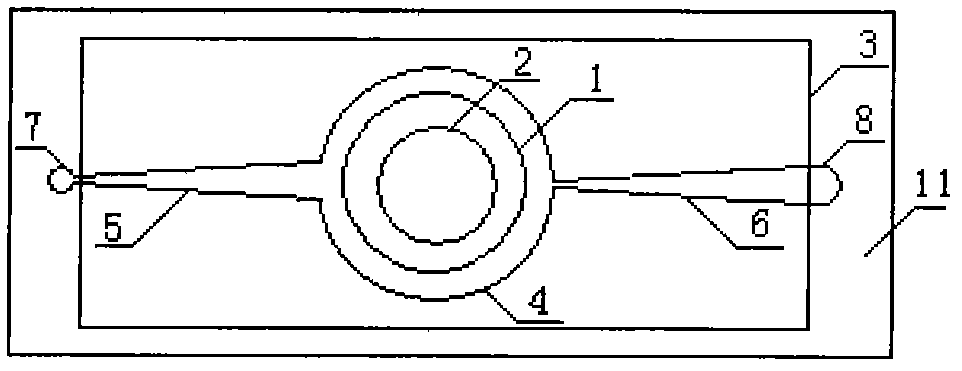
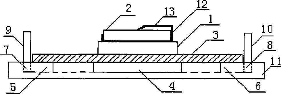
[0011] Such as figure 1 , figure 2 As shown, there is a pump chamber 4, a conical diffusion channel 5, a conical contraction channel 6, a left water hole 7 and a right water hole 8 on the pump body 11, and there is a layer of silicone rubber pump membrane on the upper surface of the pump body 11. 3. The top of the silicone rubber pump membrane 3 is bonded with the micro-vibration motor 1 with resin glue, and the button battery holder 12 is installed on the micro-vibration motor 1. The button battery is installed in the button battery holder. There is a spring piece 13 on the button battery holder. There is a plastic sheet between the sheet 13 and the button battery 2, the plastic sheet can be taken out when the micropump works, and the plastic sheet can be inserted when the micropump stops working. The pump chamber 4 is connected with the left water hole 7 through the tapered diffusion channel 5, and connected with the right water hole 8 through the tapered shrinkage channel...

Embodiment approach 2

[0016] The narrow mouth width of the tapered diffusion channel 5 and the tapered constriction channel 6 of the micropump is 100 μm, the width of the wide mouth is 500 μm, the length is 2.3 mm, and the angle is 10°; the diameter of the pump chamber of the micropump is 8 mm, and the depth is 0.5 mm The thickness of the pump membrane of the micropump is 0.25mm, and the above dimensions are the best values ​​obtained after simulation. The pump body 11 is made of glass material, and the others are the same as in Embodiment 1.

Embodiment approach 3

[0018] The narrow mouth width of the tapered diffusion channel 5 and the tapered constriction channel 6 of the micropump is 100 μm, the width of the wide mouth is 500 μm, the length is 2.3 mm, and the angle is 10°; the diameter of the pump chamber of the micropump is 8 mm, and the depth is 0.5 mm The thickness of the pump membrane of the micropump is 0.25mm, and the above dimensions are the best values ​​obtained after simulation. The pump body 11 is made of silicon material, and the others are the same as in Embodiment 1.


PUM


Abstract

A diaphragm compressed valve-less micropump belongs to the field of microfluidic delivery and control and is characterized in that the valve-less micropump is driven by a miniature vibration motor and capable of running under low voltage of 3V. The diaphragm compressed valve-less micropump mainly comprises the miniature vibration motor 1, a button cell 2, a silicon rubber diaphragm 3, a pump cavity 4, a conical diffusion passage 5, a conical contracting passage 6, a left water hole 7, a right water hole 8, a micropump inlet 9, a micropump outlet 10, a pump body 11, a button cell holder 12 and a spring piece 13. The diaphragm compressed valve-less micropump overcomes the defects of high driving voltage and complicated processing of the existing valve-less micropumps and is driven by the miniature vibration motor and capable of running under the low voltage of 3V, and accordingly, the driving voltage of the micropump is reduced and stability in running thereof is improved.

Description

technical field [0001] The invention discloses a thin-film compression valveless micropump, which belongs to the field of microfluid transmission and control, and in particular relates to a technical scheme of a valveless micropump driven by a micro vibrating motor that can work at a low voltage of 3V. Background technique [0002] Micropumps are very important actuators that precisely control and drive the flow and flow of fluids in microchannels. It can be widely used in various fields, such as micro-delivery of drugs, cell separation, cooling of integrated electronic components, micro-injection of fuel, micro-analysis in chemistry, etc. Among the actuators used in these fields, the micropump is the most important part and an important symbol of the development level of the microfluidic system. At present, the membrane-driven micropump is widely used, and its flow control is realized by the volume change of the pump chamber caused by the reciprocating motion of the drivin...

Claims


Application Information

Patent Timeline
Patent Type & Authority Applications(China)
IPC IPC(8): F04B43/04F04B53/16F04B53/00
Inventor 赵清华史健芳孙建英刘建霞
Owner TAIYUAN UNIV OF TECH
Why Eureka
Try Eureka