

Energy-saving pump with ultralow specific speed
A specific speed, energy-saving pump technology, used in pumps, pump devices, pump components, etc., can solve the problems of inability to meet the constant pressure characteristics of the conveying medium, increasing the risk of equipment failure, and reducing the lift of a single-stage pump, achieving a simple and reliable structure. , light weight, reduce hydraulic loss effect
Inactive Publication Date: 2012-07-11
GUANGZHOU GUANGYI PUMP
View PDF5 Cites 0 Cited by
- Summary
- Abstract
- Description
- Claims
- Application Information
AI Technical Summary
Problems solved by technology
However, these pumps all have some disadvantages: such as multi-stage centrifugal pumps, in order to improve the efficiency of such pumps, the usual way is to reduce the head of the single-stage pump and increase the specific speed Ns of the pump.
Due to the lower head of the single-stage pump, in order to achieve the same high pressure of the pump, it is necessary to increase the number of pump stages (that is, increase the number of pump impellers in series), and the structure of multi-stage pumps with dozens of stages becomes extremely complicated. The total length of the pump (or height) increases, the weight increases, and the cost increases substantially at the same time
The complex multi-stage pump structure increases the risk of equipment failure and troublesome maintenance
In addition, the impeller channel of the pump with low flow rate, high lift and ultra-low specific speed is short and narrow. To process a narrow and long impeller channel, the current process often uses stamping and welding stainless steel plate impellers, which greatly increases the manufacturing cost of the pump; and Due to the axial friction between the impeller and the casing, the vortex pump has a short working life and poor cavitation performance. It is only suitable for working conditions with a lift below 200M and infrequent startup; reciprocating pumps have advantages in conveying small flow and high lift media Certain advantages, higher efficiency than centrifugal pumps, but reciprocating pumps have inevitable disadvantages: unstable flow, poor reliability, frequent maintenance; large vibration, high noise
[0004] To sum up, the above categories of products can no longer meet the requirements of energy saving, low cost, simple structure, and convenient maintenance, and at the same time, they cannot meet the constant pressure characteristics required by the conveying medium.
Method used
View moreImage
Smart ImageViewing Examples

Examples
Embodiment 1
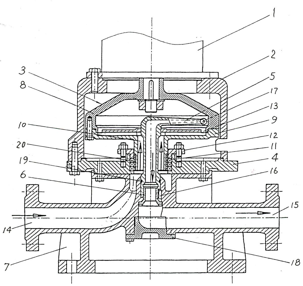
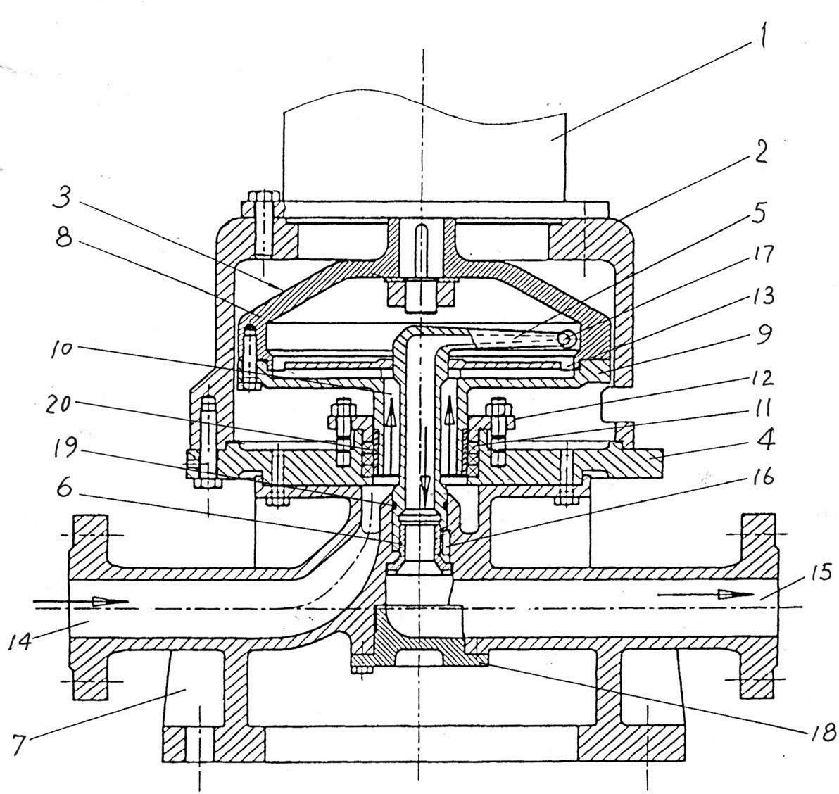
[0026] Embodiment 1. The water inlet pipe 14 and the water outlet pipe 15 of the base 7 are placed symmetrically and horizontally in the base 7 .
Embodiment 2
[0027] Embodiment 2. An O-shaped sealing ring 19 is arranged between the liquid collecting pipe 5 and the center hole of the base 7 .
Embodiment 3
[0028] Embodiment 3. An inspection cover 18 is provided at the lower end of the center hole of the base 7 .
Login to View More PUM
 Abstract
The invention discloses an energy-saving pump with ultralow specific speed, which is characterized in that a rotor consisting of a pump body and an impeller is mounted in a cavity formed by a top cap and a connecting plate, the upper end of the rotor is connected with a motor, the lower end of the rotor is arranged in a center hole of the connecting plate through a hollow shaft of the impeller, a circular water outlet is arranged at the outer edge of the impeller, a base is connected with the connecting plate, a vertical pipe of an inverted-L-shaped water collection pipe is arranged in the hollow shaft of the impeller, the lower portion of the vertical pipe is fixed to the center hole of the base by a positioning sleeve in a threaded connection manner, a flat key is arranged between the positioning sleeve and the center hole, a cross pipe of the water collection pipe is arranged above the impeller, a water inlet is arranged at the outer end of the cross pipe, a water inlet pipe at the base is communicated with the hollow shaft, and a water outlet pipe is communicated with the water collection pipe. The energy-saving pump is simple in structure, reliable in running, low in flow, high in lift, high in performance adaptability and efficiency and reliable in sealing performance, and is particularly suitable for occasions having requirements for low flow, high lift and constant pressure.
Description
technical field [0001] The invention relates to the technical field of pumps, in particular to an ultra-low specific speed energy-saving pump, which is especially suitable for use in occasions with small flow rate, high lift and constant pressure conveying medium. Background technique [0002] The pump is a machine that converts the mechanical energy of the prime mover into liquid energy through the impeller. The specific speed of the pump Ns is an important parameter used to quantify the performance of the pump. The lower the specific speed of the pump, the smaller the pump flow and the higher the lift at a certain speed. . The lower the specific speed, the shorter the flow path of the pump and the lower the pump efficiency will be. For the pump with a specific speed Ns≤30, it is usually called an ultra-low specific speed pump. Small flow and high head centrifugal pumps are used in small boiler water supply, fire protection stability, It is widely used in petrochemical, ch...
Claims
Login to View More Application Information
Patent Timeline
 Patent Type & AuthorityApplications(China)
IPC IPC(8): F04D13/06F04D29/22F04D29/42F04D29/08
Inventor刘龙珍黄思
OwnerGUANGZHOU GUANGYI PUMP