Space-wedged-type pressurizing mechanism and combined-type friction transmission wheel with same

A technology of pressurizing mechanism and friction transmission, which is applied in the direction of transmission, gear transmission, and components with teeth, etc., and can solve problems such as fatigue pitting, strong axial joint force/compression force, wear and crushing, etc. , to achieve the effect of high working reliability, long life and high transmission efficiency

Active Publication Date: 2012-07-11
洪涛
View PDF8 Cites 19 Cited by
  • Summary
  • Abstract
  • Description
  • Claims
  • Application Information

AI Technical Summary

Problems solved by technology

However, because the axial engaging force/pressing force corresponding to the transmitted torque provided by the principle of pressurization is too strong, although it meets the requirement that the friction surfaces b

Method used


Image

  • Space-wedged-type pressurizing mechanism and combined-type friction transmission wheel with same
  • Space-wedged-type pressurizing mechanism and combined-type friction transmission wheel with same
  • Space-wedged-type pressurizing mechanism and combined-type friction transmission wheel with same

Examples


Example Embodiment

[0033] Embodiment 1: One-sided mobile combined friction transmission wheel W1

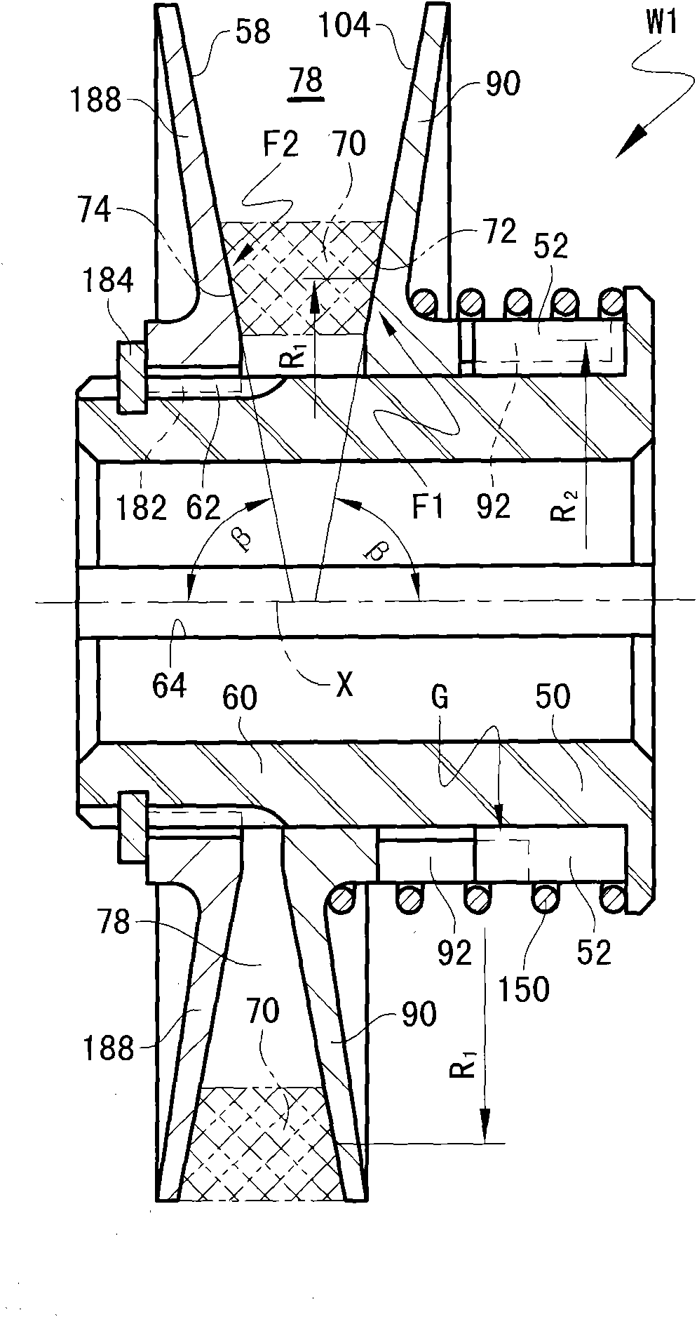
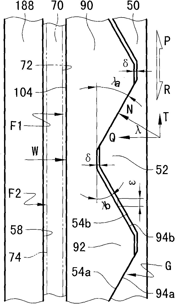
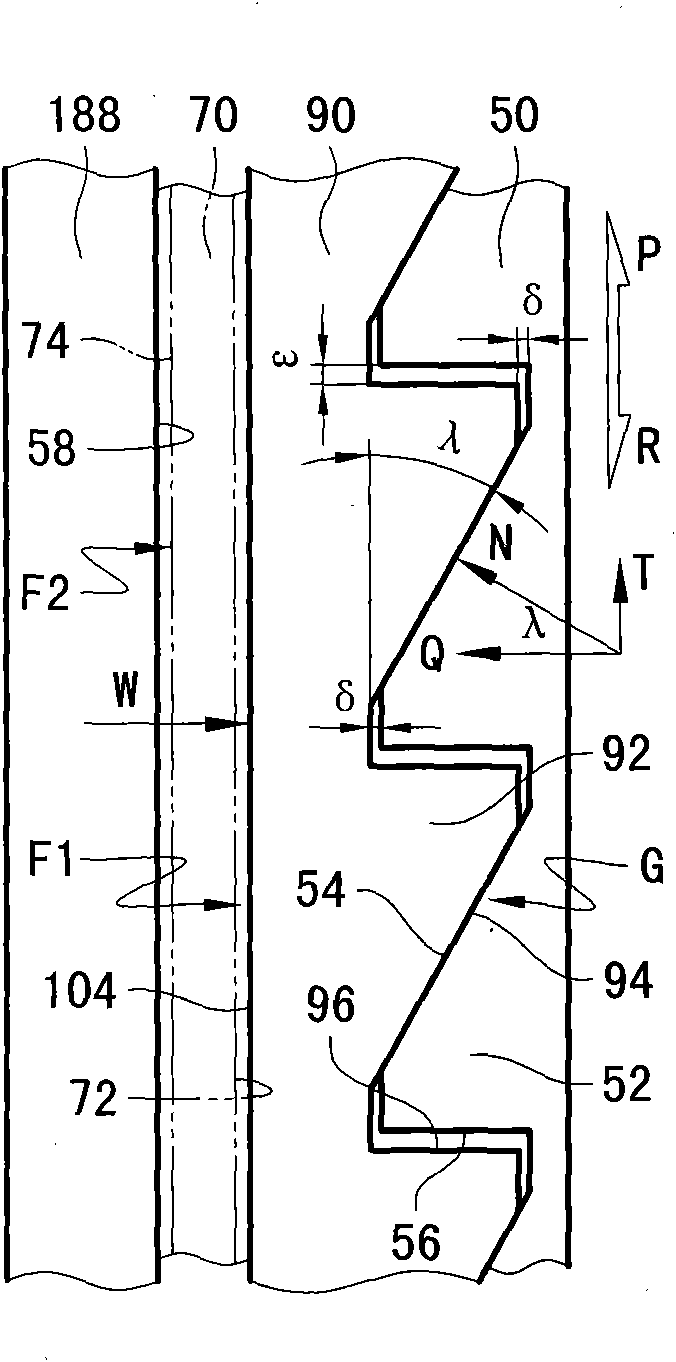
[0034] see figure 1 , Figure 2A-2B , the drive wheel W1 comprises a guide 50 formed around the axis X, preferably in the shape of a stepped ring. On the inner end surface of the outer ring side, a group of helical guide teeth 52 optimally uniformly distributed around the axis X is arranged, and on the outer peripheral surface of the middle part of the tubular base body 60 used as the transmission shaft extending from the inner ring side toward the inner end, it can be The preferably ring-shaped intermediate part 90 is radially positioned slidingly. The intermediary member 90 is permanently fitted with the guide member 50 through a group of helical guide teeth 92 that are complementary to the guide teeth 52 on the end surface of the tubular section facing the guide member 50, so as to form a surface contact The rotation guiding mechanism G is the core part of the space wedging type pressurizing ...

Example Embodiment

[0056] Embodiment 2: One-side mobile combined friction transmission wheel W4 with adjustable speed ratio

[0057] like Figure 5 As shown, as a modification to the transmission wheel W1, the guide member 50 itself becomes a solid transmission shaft in the shape of a stepped shaft, and since the rotation guide mechanism G is set as a peripheral spiral type that can only be pressurized in one direction, the transmission wheel W4 is therefore It will only be possible to transmit torque in one direction. Correspondingly, the guide member 50 may be directly provided with a limiting flange 68 for forming an axial force closed interference connection. In order to actively change the transmission speed ratio, the transmission wheel W4 also includes an adjustment mechanism D. The mechanism D includes an external helical tooth 138 arranged on the outer peripheral surface of the tubular base of the intermediary member 90, and an internal helical tooth 136 provided on the outer side of ...

Example Embodiment

[0060] Embodiment 4: Gear transmission type combined friction transmission wheel W5 with adjustable speed ratio

[0061] like Image 6 As shown, compared with the transmission wheel W4, the difference of the transmission wheel W5 is only that the adjustment mechanisms Da and Db for changing the transmission speed ratio are set as two gear mechanisms. Wherein, on the outer peripheral surface of the reference section 51 of the guide member 50, a control force output gear ring 130 is fixedly connected via, for example, a flat key 134 and a snap ring 184a, and gear teeth 132 are arranged on the outer peripheral surface thereof. The double gear ring 140 is circumferentially connected to the outer peripheral surface of the tubular base of the intermediary member 90 through a spline pair, and two sets of double gear teeth 144 and 146 are respectively arranged on the outer end / right end of the outer peripheral surface. The first duplex gear 190 is rotatably fixed to the first gear se...


PUM


Abstract

The invention discloses a space-wedged-type pressurizing mechanism and a combined-type friction transmission wheel with the same. The space-wedged-type pressurizing mechanism mainly comprises a rotary guide mechanism G, wherein the rotary guide mechanism G is provided with a guide piece and a middle part which rotate around the same axis and are respectively provided with a guide surface; and when the rotary guide mechanism G is meshed, a rising angle Lambda of the abutting part between the guide surfaces of the guide piece and the middle part is more than Zetamax and is less than Ximin, wherein the Zetamax and the Ximin are respectively the maximum one in all minimum values and the minimum one in all maximum values of the rising angle Lambda which ensures that a guide friction pair formed at the abutting part can be self-locked. The friction transmission wheel provided with the pressurizing mechanism has the advantages that the axial pressing force is less than that of the prior art, but the transmission efficiency is higher, the working reliability is higher, the working life is longer and the mechanical wear is less.

Description

[0001] related application [0002] The present invention is a subordinate patent application of the Chinese patent applications 201010222712.X and 201020186785.3 named space wedging friction overrunning clutch proposed by the present applicant. The entire contents of the published prior two patent applications are hereby incorporated by reference. technical field [0003] The present invention relates to a transmission device in the field of mechanical transmission that transmits rotary motion with a variable or fixed speed ratio by means of a rigid or annular flexible intermediate transmission member, and particularly relates to an automatic pressurization mechanism that provides axial engagement force for the device , and a combined friction transmission wheel that utilizes the mechanism to drive the movement of the intermediate transmission member. Background technique [0004] The cam-type pressing mechanism and steel ball / column V-groove type pressing mechanism with a...

Claims


Application Information

Patent Timeline
IPC IPC(8): F16D41/06F16H55/32F16H55/52F16H3/22
Inventor 洪涛
Owner 洪涛
Why Eureka
Try Eureka