
Drying device

A drying device and drying technology, which can be applied in the directions of drying gas arrangement, drying chamber/container, non-progressive dryer, etc., can solve the problems of long cylinder and bulky device as a whole.

Active Publication Date: 2012-07-11
MUTSUMI GIKEN
View PDF6 Cites 14 Cited by
  • Summary
  • Abstract
  • Description
  • Claims
  • Application Information

AI Technical Summary

Problems solved by technology

The trommel sieve has disadvantages that the cylinder is long and the whole device is bulky because it needs to move and dry the object to be dried while being rotated and stirred.

Method used


Image

  • Drying device
  • Drying device
  • Drying device

Examples


Embodiment Construction

[0029] The embodiment of the present invention will be described according to the figures below. However, the embodiments shown below are for the purpose of embodying the technical idea of ​​the present invention, and the drying device is illustrated, and the present invention does not specify the following drying device in particular. In addition, in order to make the claims easier to understand, this specification attaches numbers corresponding to the parts shown in the embodiments to the parts shown in the claims and the summary of the invention. However, the parts shown in the claims are by no means the parts that specify the embodiment.

[0030] The drying device of the present invention can be used, for example, to dry the dehydrated filter cake obtained by dehydrating the waste liquid of an electroplating factory with a filter press to a powder of a predetermined particle size. Since the dehydrated filter cake contains as much as 70% to 90% (weight ratio) of water, the...


PUM


Abstract

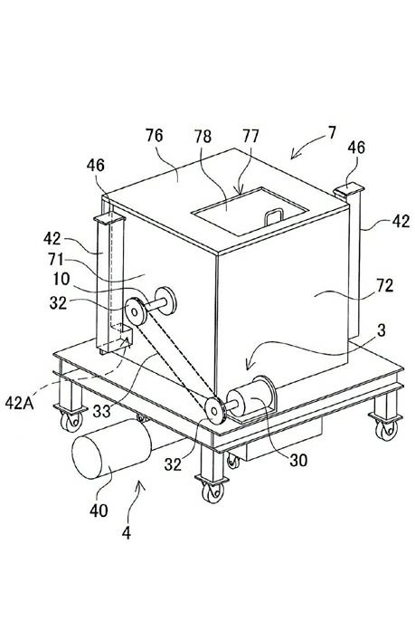
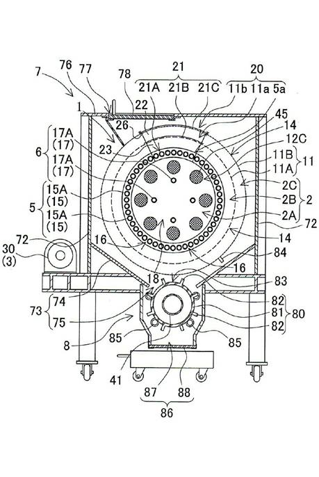
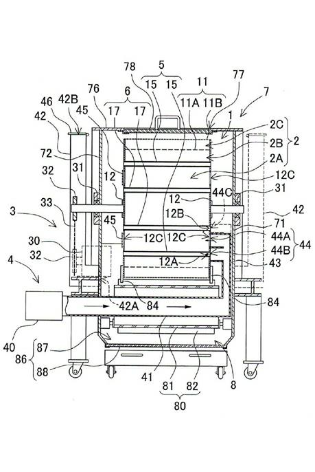
The invention provides a drying device, which comprises a cylindrical filter cartridge 11 coiled by a porous plate 13. The two ends of the cylindrical filter cartridge 11 are sealed by end plates 12. The inner side of the cylindrical filter cartridge 11 is served as a rotary barrel 1 for a drying chamber 2. The rotary barrel is driven to rotate by a drive mechanism 3. A heating air supply mechanism 4 forcibly sends heating air into the rotary barrel 1. In the rotary barrel 1, a plurality of rods 15 are arranged to be away from the inner side of the filter cartridge 11 so as to be into a cylindrical rod cylinder 5 and divide the drying chamber 2 into a first drying chamber 2A and a second drying chamber 2B. Due to the adoption of the drying device, materials to be dried are fed into the first drying chamber 2A through an opening part 20 and are dried in the first drying chamber 2A of the rotary barrel 1. Therefore, the materials fall through a dropping gap 16 into the second drying chamber 2B. Then the materials are further dried in the second drying chamber 2B and are discharged to the outside through the through holes 14 of the porous plate 13.

Description

technical field [0001] The present invention relates to a drying device for drying objects to be dried into powder, such as dehydrating the waste liquid and sludge discharged from various factories such as electroplating factories, paper factories and pharmaceutical factories, etc. through a filter press, etc. Optimum drying equipment for drying waste, etc. Background technique [0002] As far as the drying device is concerned, a trommel screen can be used. (Refer to Patent Document 1) [0003] In the trommel screen, the drum and the central axis of rotation are arranged on a descending slope. The object to be dried inside is moved and dried in the cylinder inclined at a downward slope while rotating. The trommel sieve has disadvantages that the cylinder is long and the whole device is bulky because it needs to move and dry the to-be-dried object loaded inside while rotating and stirring. Prior Art Documents: Patent Document 1 - Japanese Patent Publication No. 2001-19848...

Claims


Application Information

Patent Timeline
Patent Type & Authority Applications(China)
IPC IPC(8): F26B11/02F26B21/00F26B25/08F26B25/12
Inventor 黑田睦
Owner MUTSUMI GIKEN
Learn More