Optical-fiber curing method of frameless optical induction ring of optical-fiber gyroscope

A fiber optic gyroscope and curing method technology, applied in Sagnac effect gyroscopes and other directions, can solve the problems of fiber optic gyroscope drift, fiber breakage, skeleton deformation, etc., and achieve the effects of strong operability, cost reduction, and simple structure

Inactive Publication Date: 2012-07-11
SOUTHEAST UNIV
View PDF3 Cites 12 Cited by
  • Summary
  • Abstract
  • Description
  • Claims
  • Application Information

AI Technical Summary

Problems solved by technology

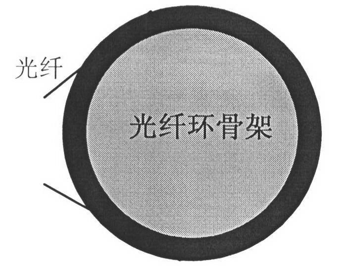
[0010] First, in the long-term application of the fiber optic gyroscope, the metal aluminum alloy material will cause the skeleton to deform, which will squeeze the fiber optic induction loop and cause the fiber to break;
[0011] Second, the coefficient of thermal expansion and contraction of the metal skeleto

Method used


Image

  • Optical-fiber curing method of frameless optical induction ring of optical-fiber gyroscope
  • Optical-fiber curing method of frameless optical induction ring of optical-fiber gyroscope
  • Optical-fiber curing method of frameless optical induction ring of optical-fiber gyroscope

Examples


Embodiment Construction

[0032] like Figure 6 , the implementation steps of the present invention are as follows:

[0033] (1) Step 1:

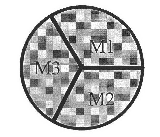
[0034] according to image 3 In this way, the cylindrical inner frame around which the optical fiber ring is wound is axially divided into three equal parts, and divided into three modules: M1, M2, M3, and there is a gap of 1.5mm to 2.5mm between adjacent modules;

[0035] (2) Step 2:

[0036] The baffles on both sides of the frame around which the optical fiber ring is wound are respectively in accordance with Figure 4 , Figure 5 Equally divided into three lobes, one side is A, B, and C, and the other side is D, E, and F. There is a gap of 0.5mm to 1.0mm between adjacent lobes. The orthographic projections of the D lobe and F lobe overlap, the B lobe overlaps the orthographic projections of the D lobe and E lobe on the opposite side, and the C lobe overlaps the orthographic projections of the E and F lobes on the opposite side;

[0037] (3) Step 3:

[0038...


PUM


Abstract

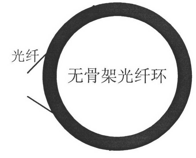
The invention discloses an optical-fiber curing method of a frameless optical induction ring of an optical-fiber gyroscope. The optical-fiber curing method comprises the following steps: a detachable device for separating a optical-fiber ring from a frame is designed according to the structure characteristic of the optical-fiber induction ring; the winding of thousands of meters of optical fibers can be met on the device according to a four-pole symmetrical method; after the optical fibers are wound, the separation of the optical-fiber ring from the frame can be realized; in addition, by combination with a winding process of the frameless optical-fiber induction ring, gluing and curing of the optical-fiber ring are carried out step by step, and then the frameless optical-fiber induction ring is realized. The optical-fiber curing method has the characteristics that the optical-fiber winding is realized on a frame optical-fiber ring winding mechanism without special design, the structure is simple, the operability is strong, the temperature stability is good and the reliability is high.

Description

technical field [0001] The invention belongs to the technical field of inertial sensor design, relates to a high-precision and high-stable interferometric optical fiber gyroscope solidification technology for a skeletonless optical fiber induction loop, and relates to a fiber optic solidification method for a skeletonless optical induction loop of an optical fiber gyroscope. Background technique [0002] The fiber optic gyroscope is an optical interferometer based on the Sagnac effect. It has the advantages of all-solid-state design, simple structure, shock resistance, wide frequency band, long mean time between failures, and low power consumption. The fiber optic gyroscope is used in the strapdown inertial navigation system The application of strapdown technology makes the advantages of strapdown technology more prominent, and has broad application prospects in navigation control systems, attitude control systems, and related fields such as aviation, aerospace, navigation, a...

Claims


Application Information

Patent Timeline
IPC IPC(8): G01C19/72
Inventor 王立辉徐晓苏刘锡祥张涛闫捷
Owner SOUTHEAST UNIV
Why Eureka
Try Eureka