Dynamic balance assembly testing device of engine rotors

A technology of rotor dynamic balance and test device, which is applied in static/dynamic balance test, measurement device, machine/structural component test, etc., can solve the problems of difficult assembly, low efficiency, complicated equipment operation, etc., and achieve high economic value and practical value

Active Publication Date: 2012-07-11
SHENYANG LIMING AERO-ENGINE GROUP CORPORATION
View PDF4 Cites 17 Cited by
  • Summary
  • Abstract
  • Description
  • Claims
  • Application Information

AI Technical Summary

Problems solved by technology

[0003] For the dynamic balance of the aero-engine rotor assembly, due to the large size, complex structure and high balance precision requirements, the current assembly balance method, tooling and equipment operation are complicated and cost a lot of money Man-hours, difficult assembly, low efficiency, low precision of dynamic balance

Method used


Image

  • Dynamic balance assembly testing device of engine rotors
  • Dynamic balance assembly testing device of engine rotors
  • Dynamic balance assembly testing device of engine rotors

Examples


Embodiment 1

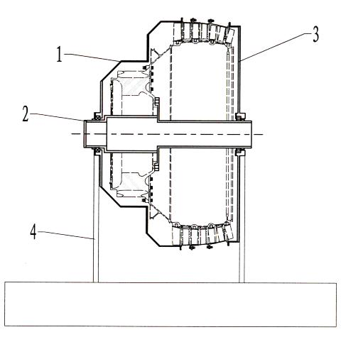
[0020] This embodiment provides a dynamic balance test device for an engine rotor. The balance test device includes a front balance process casing 1, a balance mandrel 2, a rear balance process casing 3, and a balance machine 4;

[0021] Among them: the front balance process casing 1 is connected to the front stator of the rotor with the stator of the engine, the rear balance process casing 3 is connected to the rear casing of the rotor with the engine stator; the front balance process casing 1 and the rear balance process casing 3 They are respectively installed at the front and rear ends of the balance mandrel 2. The rotor with the stator of the engine is respectively connected with the front balance process case 1 and the rear balance process case 3 through the stator, and finally forms a balance unit body with the balance mandrel 2, and relies on the balance mandrel 2 Supported on a balancing machine.

[0022] The structure of the front balance process casing 1 is a steppe...

Embodiment 2

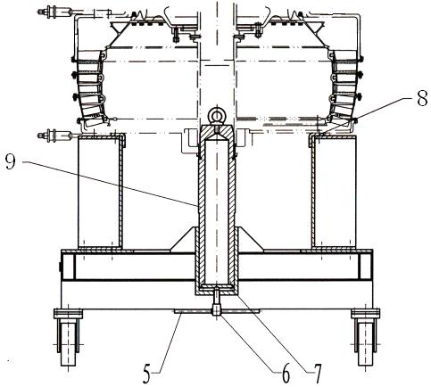
[0027] This embodiment provides an engine rotor dynamic balance assembly and transportation device, the device includes a trigger rod 5, a push rod 6, a baffle plate 7, a support block 8, and a column 9;

[0028] Among them: the lever 5 and the ejector rod 6 are fixedly installed, and have the function of adjusting the vertical position of the ejector rod 6, the baffle plate 7 is located at the top of the ejector rod 6, the column 9 can move the vertical position according to the adjustment of the ejector rod 6, and the balance mandrel 2 In contact with the column 9, the support block 8 is located between the engine stator casing and the assembly vehicle, and the column 9 is located between the engine rotor and the assembly vehicle.

[0029] The assembly vehicle is provided with a multi-functional supporting block 8 and a multi-functional ejector rod 6 for adjusting the vertical movement of the assembly unit body, and is convenient for transportation in the final state.

[003...


PUM


Abstract

The invention relates to a dynamic balance assembly testing device of engine rotors, which comprises a front balance process casing, a balance mandrel, a rear balance process casing, a balancer, a pulling rod, an ejection rod, a baffle plate, a support block and an upright column, wherein in the balance state, the front balance process casing is connected with the front part of a stator outside an engine rotor, the rear balance process casing is connected with the rear part of a stator outside an engine rotor, the front balance process casing and the rear balance process casing are respectively arranged at the front end and the rear end of the balance mandrel and are arranged on the balancer through the balance mandrel; and in the assembly state, engine rotors of the front balance process casing and the rear balance process casing are arranged on an assembly vehicle, the support block is positioned between an engine stator casing and the assembly vehicle, and the upright column is arranged between the engine rotors and the assembly vehicle. The dynamic balance assembly testing device of the engine rotors, which is provided with the stators, solves the dynamic balance assembly problem of a special structure, realizes multifunctional assembly and transportation and has higher economic and practical values.

Description

technical field [0001] The invention relates to the field of aviation rotor dynamic balancing process equipment and equipment, and in particular provides an engine rotor dynamic balancing testing device. [0002] Background technique [0003] For the dynamic balance of the aero-engine rotor assembly, due to the large size, complex structure and high balance precision requirements, the current assembly and balance methods, tooling and equipment operations are complicated, consume a lot of man-hours, assembly is difficult, efficiency is low, and the precision of dynamic balance is low. [0004] Contents of the invention [0005] The purpose of the present invention is to improve the efficiency of dynamic balance and ensure the accuracy, and especially provides a dynamic assembly balance test device for engine rotors. [0006] The invention provides an engine rotor dynamic balance test device, characterized in that: the engine rotor dynamic balance test device includes a ...

Claims


Application Information

Patent Timeline
Patent Type & Authority Applications(China)
IPC IPC(8): G01M1/14H02K15/16
Inventor 杜立峰可成河时金辉巩孟祥宋涛
Owner SHENYANG LIMING AERO-ENGINE GROUP CORPORATION
Why Eureka
Try Eureka