Unlock instant, AI-driven research and patent intelligence for your innovation.

Low-power-consumption clock frequency detection circuit

A technology of clock frequency and detection circuit, applied in the direction of frequency measurement device, etc., can solve the problem of leakage of confidential data by security chip, and achieve the effect of preventing information leakage

Active Publication Date: 2012-07-11
SHENZHEN STATE MICRO TECH
View PDF4 Cites 17 Cited by
  • Summary
  • Abstract
  • Description
  • Claims
  • Application Information

AI Technical Summary

Problems solved by technology

[0003] The present invention provides a low-power consumption clock frequency detection circuit in order to solve the technical problem of leaking confidential data due to fault attacks on security chips in the prior art

Method used


Image

  • Low-power-consumption clock frequency detection circuit
  • Low-power-consumption clock frequency detection circuit
  • Low-power-consumption clock frequency detection circuit

Examples


Embodiment Construction

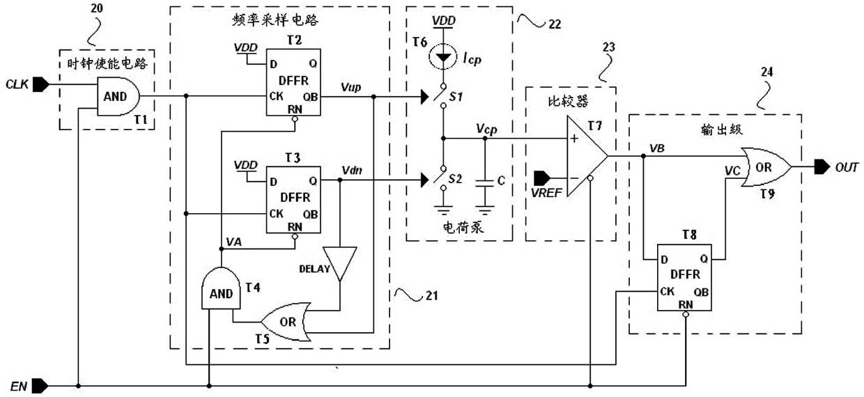
[0019] See figure 1 and figure 2 . The low power consumption clock frequency detection circuit of the present invention includes a clock enabling circuit 20 , a frequency sampling circuit 21 , a charge pump 22 , a comparator 23 and an output stage 24 connected in sequence. in:

[0020] The input terminals of the clock enable circuit 21 are respectively connected to the system clock terminal CLK and the system enable terminal EN, and output the system clock when the enable signal input by the system enable terminal is valid.

[0021] The system clock terminal CLK is used to input the system clock, and the system enable terminal EN is used to input the system enable signal.

[0022] In this specific embodiment, the clock enabling circuit 21 is composed of a first AND gate T1, and the two input terminals of the first AND gate T1 are respectively connected to the system clock terminal CLK and the system enable terminal EN.

[0023] The input terminal of the frequency sampling...


PUM


Abstract

The invention discloses a low-power-consumption clock frequency detection circuit, which comprises a system clock end, a system enabling end, a clock enabling circuit, a frequency sampling circuit, a charge pump, a comparer and an output stage, wherein when an enabling signal which is input by the system enabling end is effective, the clock enabling circuit outputs a system clock; the frequency sampling circuit samples a rising edge of the system clock and outputs two channels of control signals with opposite output levels according to a sampling result; the charge pump performs periodic charging and discharging according to the two channels of control signals; the comparer compares an output voltage of the charge pump with a reference voltage and then outputs a comparison signal; the reference voltage is a maximum voltage of the charge pump when the frequency of the system clock is a reference frequency; and the output stage processes the comparison signal which is output by the comparer at the rising edge of the system clock and outputs a corresponding detection level when the frequency of the system clock deviates from the reference frequency. The low-power-consumption clock frequency detection circuit can be applied to anti-clock failure attack of a system on chip (SOC).

Description

technical field [0001] The invention relates to the field of security chips, in particular to a low-power consumption clock frequency detection circuit for monitoring a system clock in an information security chip. Background technique [0002] Security chips are widely used in various fields of the information society, and their main functions include secure storage, encryption, decryption, and identification of key user data. Because of the importance of the data in the security chip, the fault attack has become one of the main attack methods to obtain the data in the security chip. Fault attack refers to making the chip work under abnormal working conditions, such as abnormal voltage, temperature, clock frequency, electromagnetic environment, etc. These abnormal working conditions may induce wrong behavior of the chip and invalidate some security operations inside the chip , causing the security measures taken by the chip to be bypassed, thereby leaking confidential data...

Claims


Application Information

Patent Timeline
IPC IPC(8): G01R23/02
Inventor 王新亚吴晓勇徐浩黄浩
Owner SHENZHEN STATE MICRO TECH
Features
  • R&D
  • Intellectual Property
  • Life Sciences
  • Materials
  • Tech Scout
  • Unparalleled Data Quality
  • Higher Quality Content
  • 60% Fewer Hallucinations
Learn More