Testing device for operation of current changing chain and control method

A test device and operation test technology, which is applied in the field of power electronics, can solve the problems of many device components, large operating noise, and many maintenance tasks, and achieve low system capacity requirements, reduce power waste, and achieve simple effects

Active Publication Date: 2012-07-11
CHINA EPRI SCIENCE & TECHNOLOGY CO LTD +2
View PDF5 Cites 17 Cited by
  • Summary
  • Abstract
  • Description
  • Claims
  • Application Information

AI Technical Summary

Problems solved by technology

As a load, the resistance box will cause a large active loss and can only be used in low-power occasions; the motor can adjust the output power, but the device has many components, occupies a large area, has a large operating noise, and requires more maintenance work; the reactor Usually the external load is constant, and the output power of the cascaded converter cannot be adjusted conveniently, and the voltage level of the cascaded converter is high, so the insulation requirements for the reactor are relatively high
[0007] Due to the limitation of test load capacity and power supply capacity, it is still impossible to test the heat dissipation capac

Method used


Image

  • Testing device for operation of current changing chain and control method
  • Testing device for operation of current changing chain and control method
  • Testing device for operation of current changing chain and control method

Examples


Embodiment 2

[0048] This embodiment is basically the same as Embodiment 1, but the difference with Embodiment 1 is:

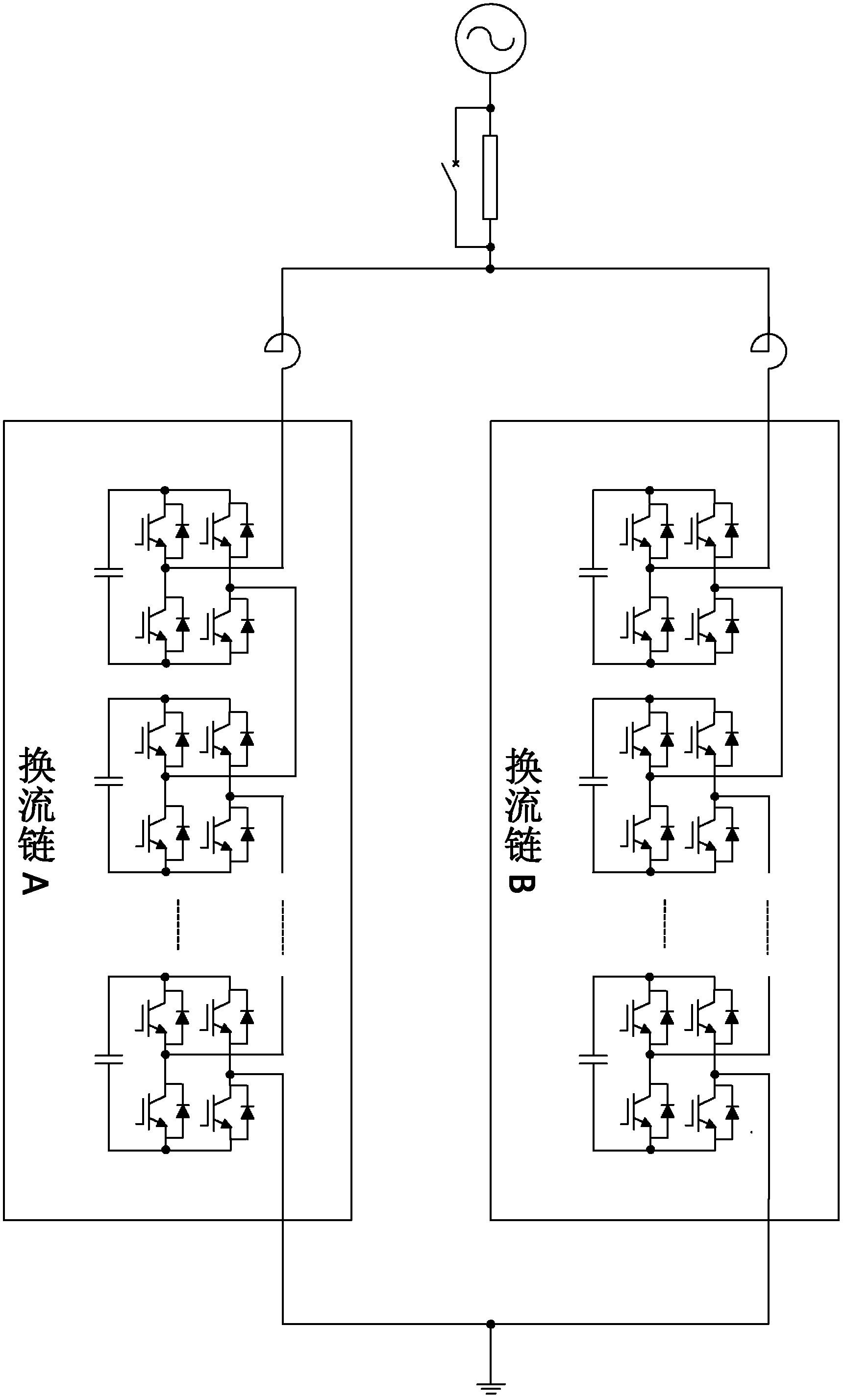
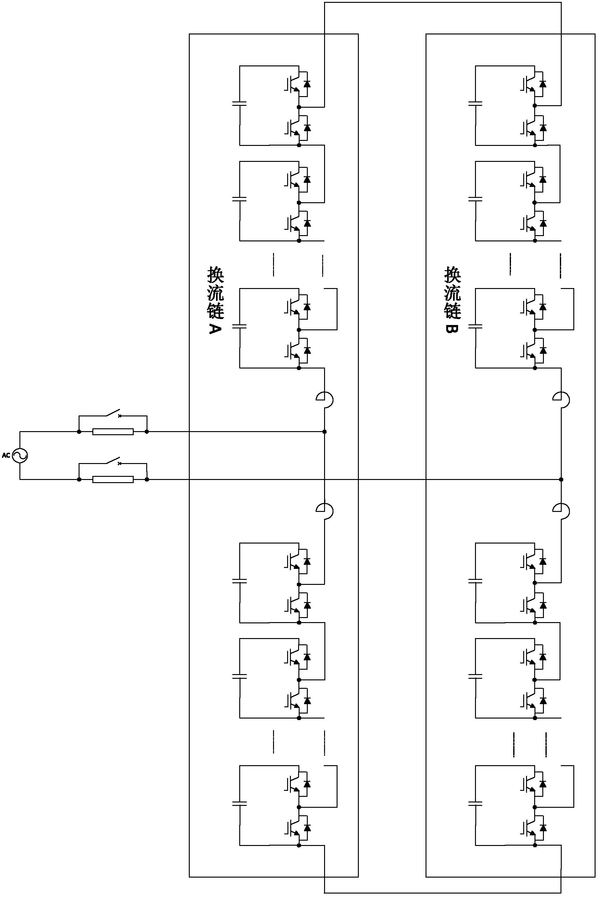
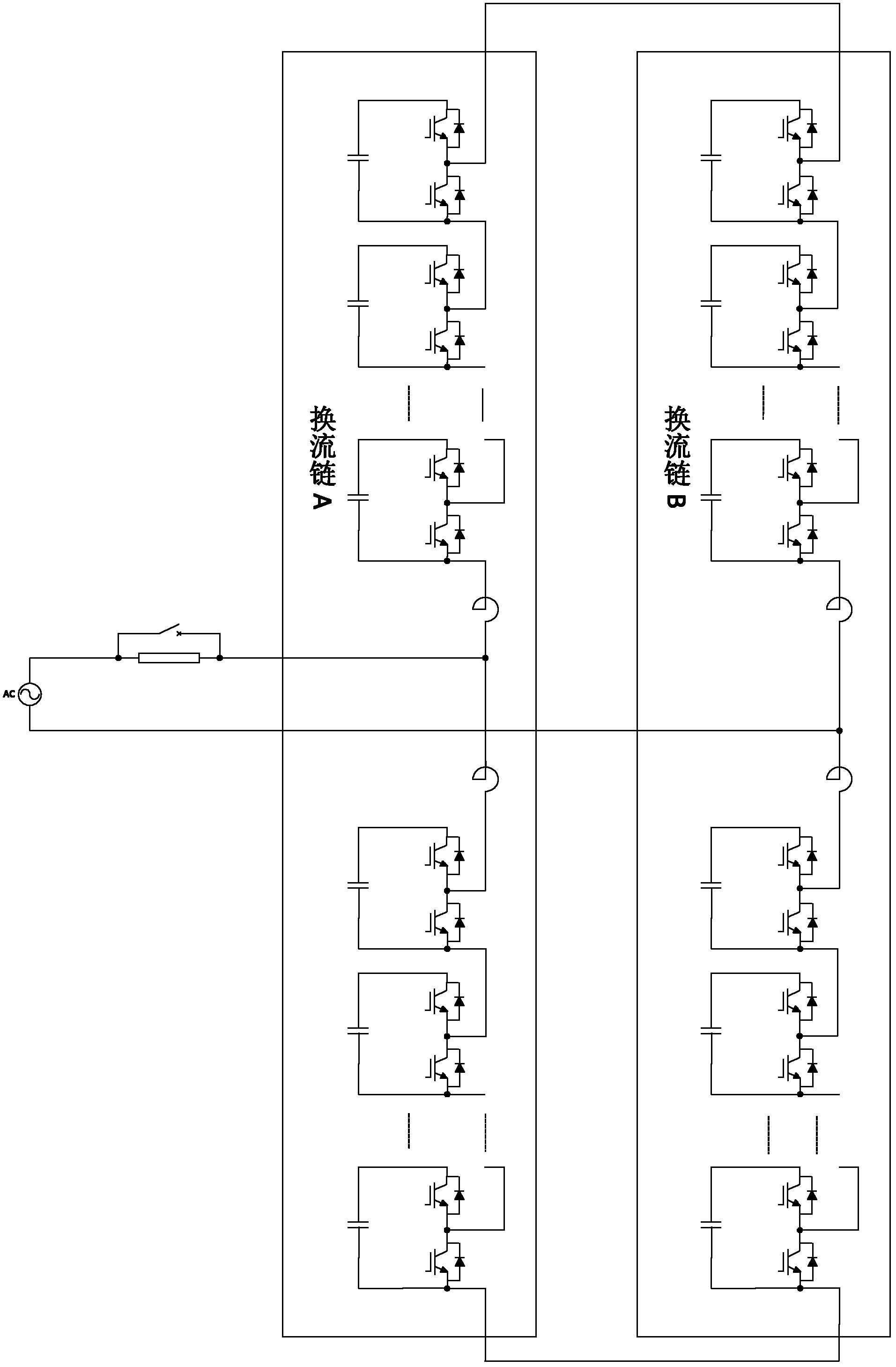
[0049] The link module of this embodiment includes a parallel half-bridge structure and capacitors; the half-bridge structure includes IGBT modules with upper and lower bridge arms, and each IGBT module includes anti-parallel IGBTs and diodes. The midpoint of the chain link module and the positive pole (or negative pole) of the DC side are used as the AC outlet, and the AC sides of each chain link module are connected end to end.

[0050] Reactors are installed between the midpoint of each commutation chain and the upper and lower link modules; connect the midpoint of one commutation chain to one end of the single-phase system through a soft starting circuit, and connect the midpoint of the other commutation chain The midpoint is connected to the other end of the single-phase system through a soft-start circuit (or not connected to a soft-start circuit). Such as figure 2...


PUM


Abstract

The invention discloses a testing device for operation of a current changing chain and a control method. The testing device comprises two current changing chains, wherein one end of each current changing chain is connected with a reactor in series; and a single-phase system transmits current to the current changing chain by a soft circuit and the reactor so as to charge the two current changing chains. Inverse outputs of the two current changing chains are started simultaneously, and the output currents are increased gradually and respectively, so that one current changing chain works in a capacitive output state, and the other current changing chain works in a sensible output state till the two current changing chains meet the testing conditions. By test, whether the current chaining chains can operate normally to meet the designed capacity and overload capability under various working conditions can be judged. The invention has the advantages that the circuit is simple, and all parts of a cascade converter can be completely utilized without need of adding a special testing part additionally; long-time and high-power test can not cause influence on the system, and the power waste is reduced; and the requirement on the system capacity is very low without need of capacity expansion and modification on a power supply.

Description

Technical field: [0001] The invention relates to the field of power electronics, in particular to a commutation chain operation test device and a control method. Background technique: [0002] The cascaded converter (namely, the converter chain) is composed of N independent full-bridge structure link modules or half-bridge structure link modules connected in series on the AC side. Each link module (also called a converter unit ) DC sides are independent of each other. After three single-phase commutation chains are connected in series with inductors, a three-phase system can be formed through Y-type or △-type connections. It can be used in various high-voltage power electronic devices. The capacitive or inductive reactive current output by the converter is within the allowable system It is continuously adjustable within the voltage range and has nothing to do with the system voltage. When the DC side of each chain link module is connected with a power supply or energy stora...

Claims


Application Information

Patent Timeline
IPC IPC(8): G01R31/00
Inventor 王轩武丹赵瑞斌王清涛郑青青李志伟李金元何维国林嘉扬
Owner CHINA EPRI SCIENCE & TECHNOLOGY CO LTD
Why Eureka
Try Eureka