Supercharge Your Innovation With Domain-Expert AI Agents!

Optical lens with antistatic coating

An optical lens and antistatic technology, applied in optics, coatings, optical components, etc., can solve the problems of anti-reflection coating mechanical and optical performance damage, high cost, etc.

Inactive Publication Date: 2012-07-11
CARL ZEISS VISION INT GMBH
View PDF9 Cites 4 Cited by
  • Summary
  • Abstract
  • Description
  • Claims
  • Application Information

AI Technical Summary

Problems solved by technology

However, inserting such an ITO layer into an anti-reflective coating has certain disadvantages, such as higher cost of coating, and damage to the mechanical as well as optical properties of the anti-reflective coating.

Method used


Image

  • Optical lens with antistatic coating
  • Optical lens with antistatic coating
  • Optical lens with antistatic coating

Examples


Embodiment Construction

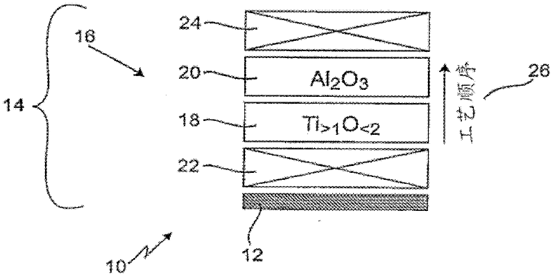
[0039] figure 1 Optical lens 10 in one embodiment is shown. The optical lens 10 has a lens element 12 provided with a coating 14 . The coating 14 includes a plurality of layers 16 that are subsequently applied.

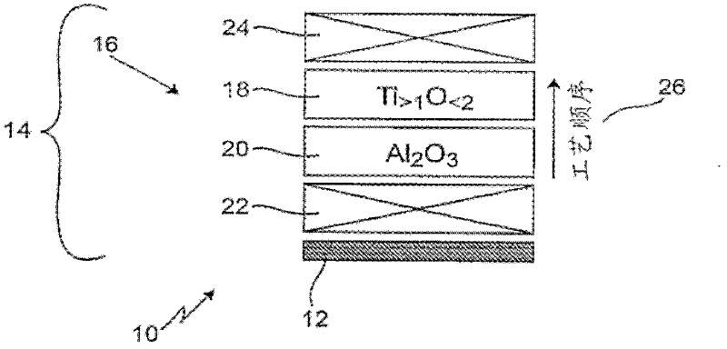
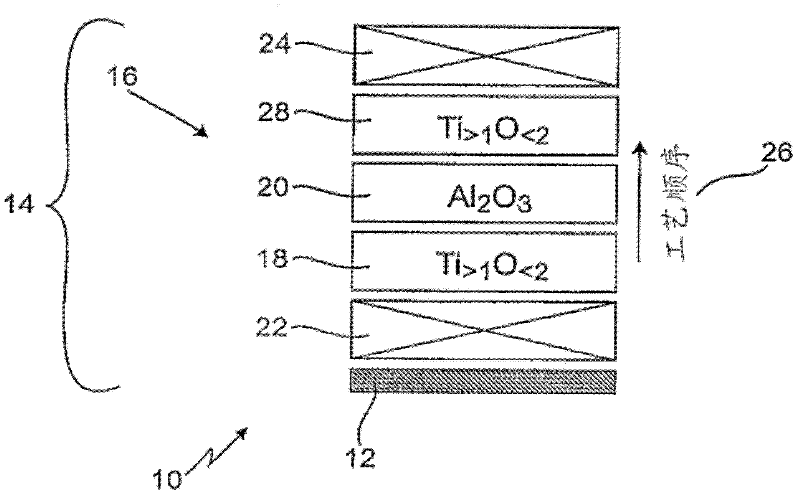
[0040] In particular, the coating 14 includes a first layer 18 made of titanium oxide (TiO 2 ) are formed in a substoichiometric ratio. Here, the term "substoichiometric" refers to the fact that oxygen deficiency dominates; this composition thus leads to Ti >1 o <2 . Made of alumina (Al 2 o 3 ) fabricated second layer 20 is disposed thereon. The substoichiometric first layer 18 and this second layer 20 together form an electrically conductive boundary layer which integrates an antistatic effect in said optical lens 10 in view of its electrical conductivity.

[0041] The arrangement of the first layer 18 and the second layer 20 within the coating 14 does not have to be at the surface of the coating 14 . Illustratively, an underlayer 22 may be provided between...


PUM


Abstract

The optical lens (10) has a lens element (12) on which several layers (16) with an anti-static coating (14) are formed for generating an anti-static effect. Two adjacent layers (18, 20) are formed with respect to the lowermost layer (22) and an upper layer (30). The stoichiometrically formed layer (18) is made of titanium oxide with specific amount of oxygen, and an aluminum oxide layer (20) is formed over the titanium oxide layer (18). An independent claim is included for method for formation of several layers of lens element.

Description

technical field [0001] The invention relates to an optical lens, in particular for use as an eyeglass lens, having a lens element and a coating which produces an antistatic effect, said coating being applied to said lens element and comprising a plurality of layers. [0002] Furthermore, the invention relates to a method for producing an antistatic coating for lens elements having a plurality of layers. Background technique [0003] Antistatic spectacle lenses are known in the art. It offers the advantage that a lower degree of dust particles adheres to the spectacle lens due to the absence of electrostatic attraction. Without an antistatic coating, eyeglass lenses become soiled more quickly and need to be cleaned more often. Furthermore, dust is often difficult to remove. For coatings of spectacle lenses, therefore, electrically conductive and thus antistatic layers are usually inserted within the coating. For this purpose, until now, a separate layer has been inserted ...

Claims


Application Information

Patent Timeline
Patent Type & Authority Applications(China)
IPC IPC(8): G02B1/10B32B33/00B32B9/04
CPCB29D11/00865G02B1/116G02C7/10G02B2207/121G02B1/16G02B1/11
Inventor A.纽弗
Owner CARL ZEISS VISION INT GMBH
Features
  • R&D
  • Intellectual Property
  • Life Sciences
  • Materials
  • Tech Scout
  • Unparalleled Data Quality
  • Higher Quality Content
  • 60% Fewer Hallucinations
Learn More