
Sealant coating machine

A glue coating machine and sealant technology, which is applied to the device, coating, optics and other directions of coating liquid on the surface, which can solve the problem of measuring the wrong cross-sectional area of ​​the sealant pattern.

Inactive Publication Date: 2012-07-11
TOP ENG CO LTD
View PDF7 Cites 1 Cited by
  • Summary
  • Abstract
  • Description
  • Claims
  • Application Information

AI Technical Summary

Problems solved by technology

However, if the position of the glass panel or the cross-sectional area sensor is changed among the portions where the cross-sectional area of ​​the sealant pattern is measured, an error occurs when measuring the cross-sectional area of ​​the sealant pattern.

Method used


Image

  • Sealant coating machine
  • Sealant coating machine
  • Sealant coating machine

Examples


Embodiment Construction

[0022] Hereinafter, a preferred embodiment of a sealant applicator according to the present invention will be described in detail with reference to the accompanying drawings.

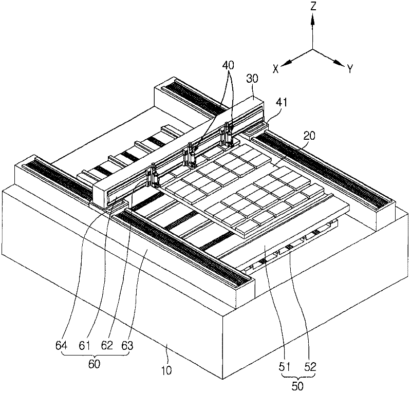
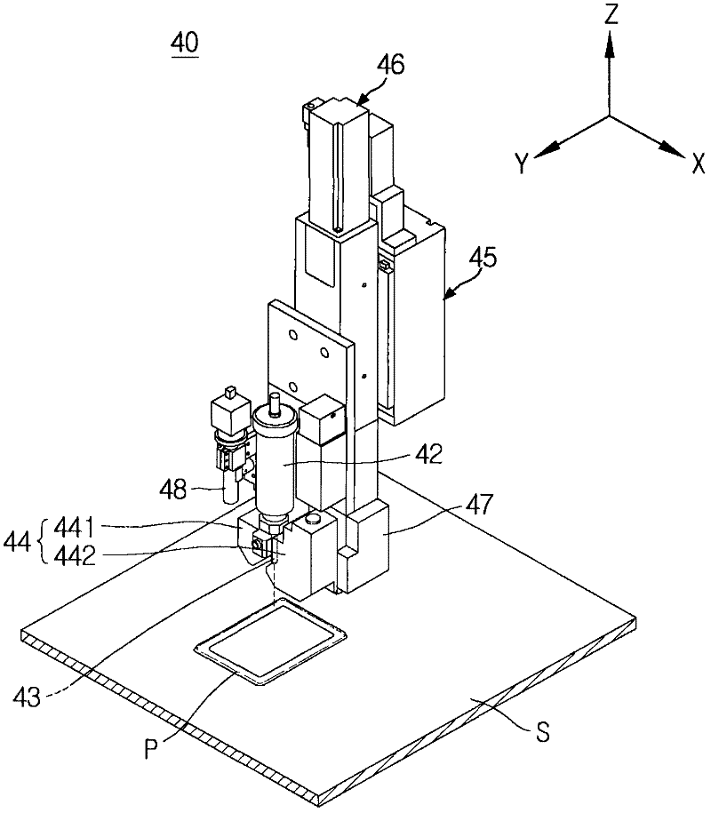
[0023] Such as figure 1 As shown, the sealant coating machine according to the embodiment of the present invention includes a frame 10, a pallet 20, a coating head unit support frame 30, a coating head unit 40, a pallet moving unit 50, a head moving unit 60, and a control unit 70( image 3 show). The pallet 20 is mounted on the frame 10 . The glass panel S is placed on the pallet 20 . The coating head unit support frame 30 is disposed above the pallet 20 and extends a predetermined length along the X-axis direction. The coating head unit 40 is movably supported by the coating head unit support frame 30 . The gantry moving unit 50 is provided on the frame 10, and moves the gantry 20 horizontally. The head moving unit 60 moves the coating head unit 40 horizontally. The control unit 70 controls the ...


PUM


Abstract

Disclosed herein is a sealant coating machine, wherein the position for preventing the breakage of a glass panel and the installation of a cross-sectional sensor on the part for measuring the cross-sectional area of the sealant can be minimally changed. Therefore, when measuring the sectional area of the sealant, no error has occurred.

Description

technical field [0001] The invention relates to a sealant coating machine for coating sealant on glass panels. Background technique [0002] In general, a flat panel display (FPD) is a thinner and lighter image display than a television or monitor with a Braun tube. Liquid crystal displays (LCDs), plasma display panels (PDPs), field emission displays (FEDs), and organic light emitting diodes (OLEDs) are representative examples of flat panel displays that have been developed and used. [0003] The LCDs of these FPDs are image displays that display desired images in a manner of independently supplying data signals based on image information to liquid crystal cells arranged in a matrix shape, and thereby controlling light transmittance of the liquid crystal cells. LCDs are thin and light, and also have many other advantages including low power consumption and low operating voltage, and thus are widely used. A typical manufacturing method of a liquid crystal panel used in such...

Claims


Application Information

Patent Timeline
Patent Type & Authority Applications(China)
IPC IPC(8): G02F1/1339B05C5/00B05C11/00B05C13/00
CPCG02F1/13G02F1/1303B05C5/00B05C5/02B05C5/0216B05C11/00B05C11/10H10K71/135
Inventor 方圭龙金锺相徐容珪金贤正
Owner TOP ENG CO LTD
Learn More