
Vibration motor and lens drive mechanism

一种振动电机、振动体的技术,应用在发电机/电动机、压电效应/电致伸缩或磁致伸缩的电动机、电气元件等方向,能够解决分散、无法驱动效率降低、加压机构按压力不稳定等问题,达到稳定驱动传递力、抑制传递不良的效果

Inactive Publication Date: 2014-10-08
TAMRON
View PDF5 Cites 0 Cited by
  • Summary
  • Abstract
  • Description
  • Claims
  • Application Information

AI Technical Summary

Problems solved by technology

In particular, in the case of a lens drive mechanism, etc., due to the limitation of the installation position, when the pressurizing mechanism of the vibration motor cannot be arranged on the same straight line as the contact portion between the driven body 200 and the output part 101, The pressing force from the pressing mechanism tends to become unstable
[0007] In addition, in the case of an ultrasonic motor, since the piezoelectric element used as a vibrating body has hysteresis between the applied voltage and the displacement amount, the positional relationship between the pressurizing mechanism and the vibrating body assumed in a static state sometimes slightly off
As a result, there is a problem that the force acting from the pressing mechanism to the vibrating body is dispersed, and the pressing cannot be performed in an optimal state, thereby reducing the driving efficiency. Therefore, further improvement is required.

Method used


Image

  • Vibration motor and lens drive mechanism
  • Vibration motor and lens drive mechanism
  • Vibration motor and lens drive mechanism

Examples


Embodiment Construction

[0024] Hereinafter, preferred embodiments of the vibration motor and the lens drive mechanism according to the present invention will be described.

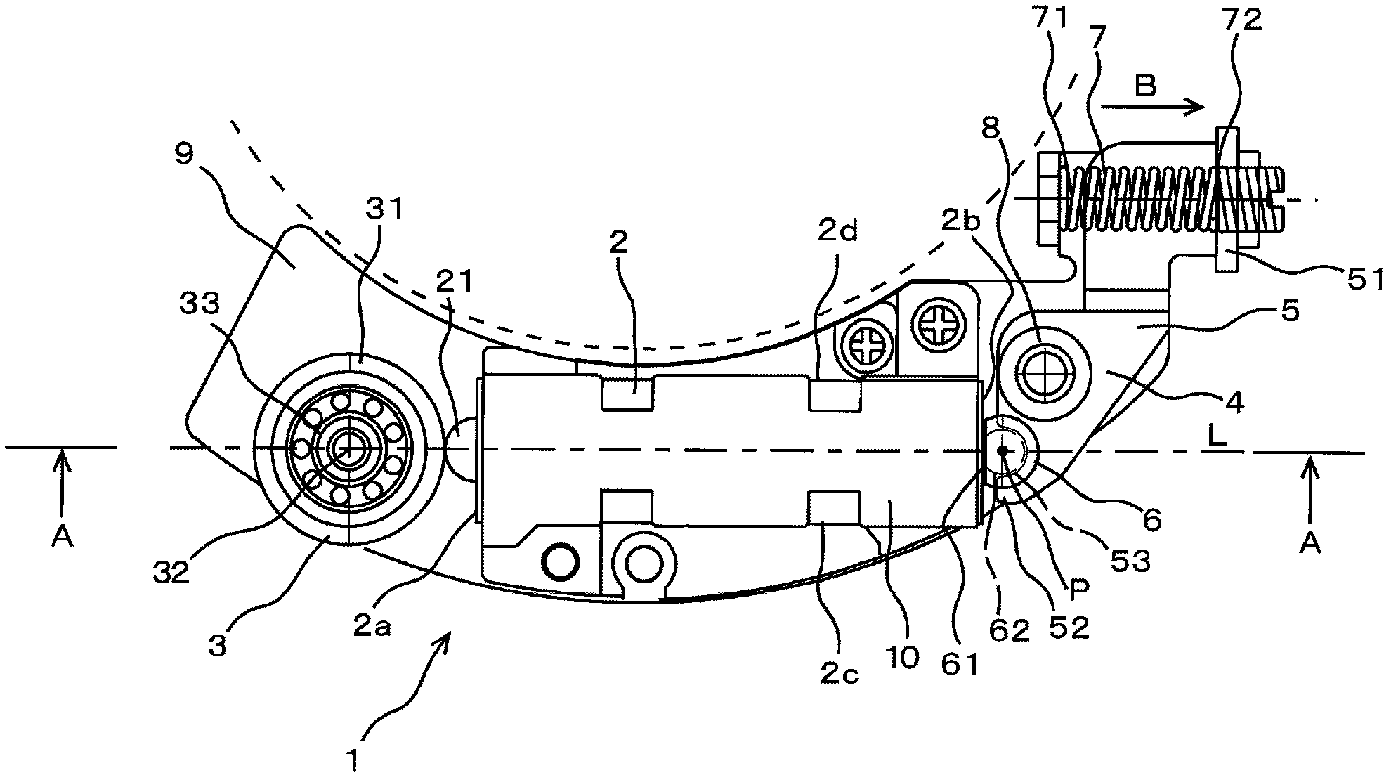
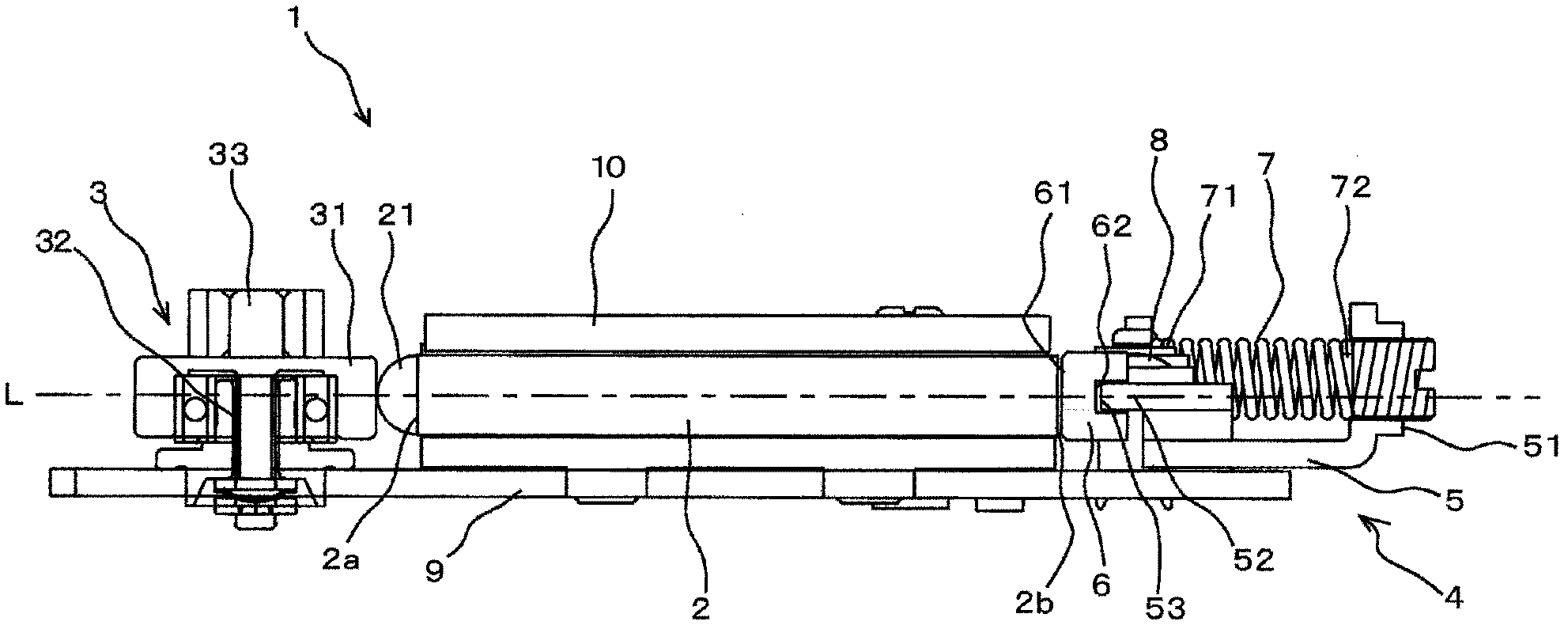
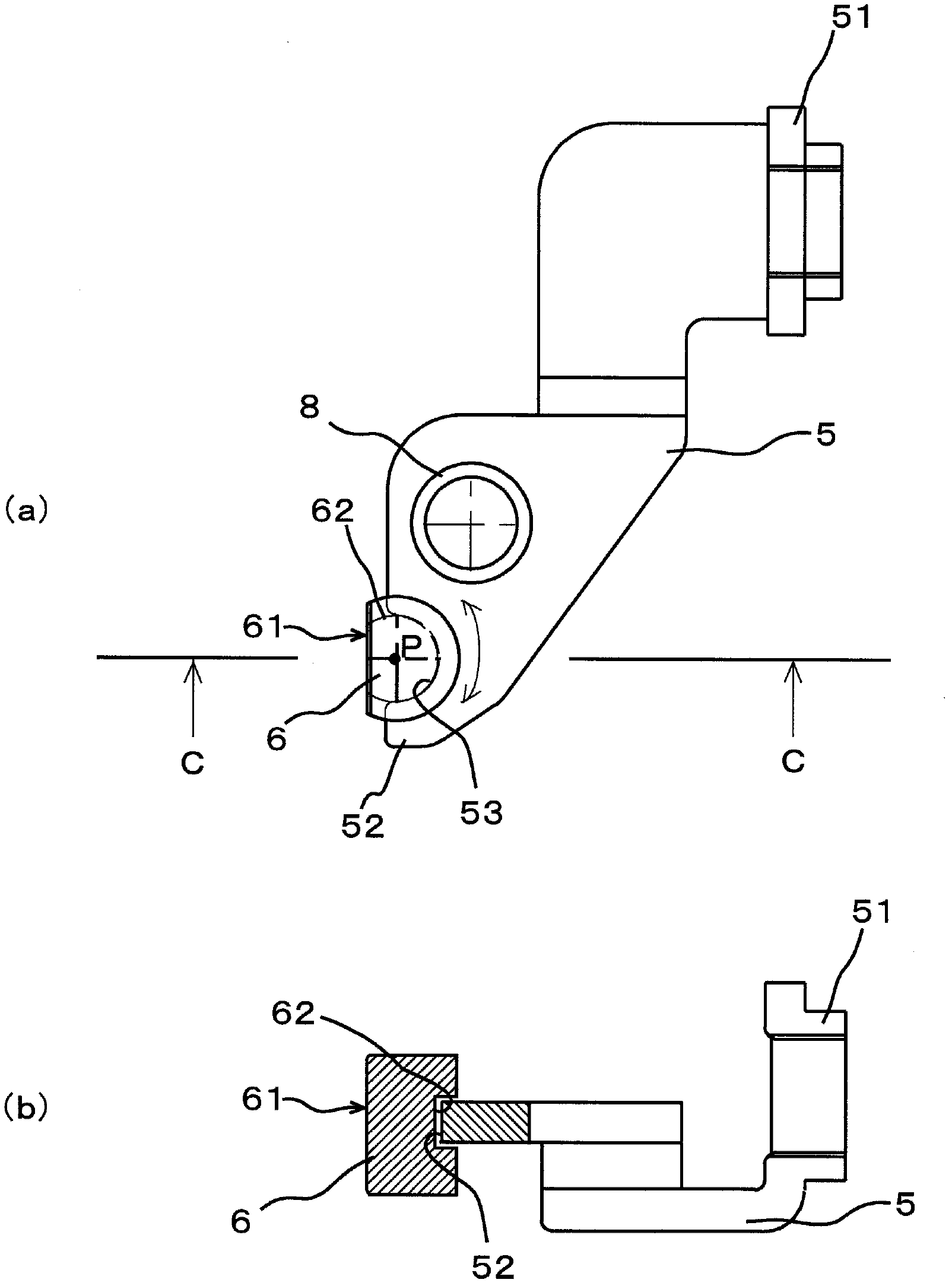
[0025] The vibration motor according to the present invention vibrates a vibrating body, presses the vibrating body to a driven body, and transmits the vibration of the vibrating body as a driving force, and includes a vibrating body and a pressurizing mechanism. figure 1 It is a plan view showing an example in which the vibration motor according to the present invention is arranged on the outer peripheral side of the lens as a driving mechanism of the imaging lens. figure 2 to include figure 1 Front view including section A-A in . Such as figure 1 and figure 2 As shown, in the vibrating body 2 of the vibrating motor 1, the output part 21 provided on the side surface 2a at one end thereof is disposed at a position abutting against the driven body 3, and is abutted against the side surface 2b at the other end side. A pres...


PUM


Abstract

The present invention provides a vibrating motor and a lens driving mechanism. The vibrating motor can press the vibrating body toward the driving body side in a stable state, thereby improving the driving efficiency. The lens driving mechanism uses the vibrating motor so that it can effectively use The lens moves. In order to achieve this object, the following vibrating motor is adopted, which vibrates the vibrating body, and presses the vibrating body on the driven body, so as to transmit the vibration of the vibrating body as a driving force, and is characterized in that it has: a vibrating body, which On the side of one end side, there is a protruding output part, and the output part is arranged in contact with the driven body; the pressing mechanism, on the side of the other end side of the vibrating body, is pressed to the driven body side The vibrating body, and the pressurizing mechanism is provided with a pressurizing correction part rotatably provided at the contact position between it and the vibrating body, and the pressurizing mechanism presses the vibrating body to a predetermined direction through the pressurizing correcting part. Apply pressure in the direction.

Description

technical field [0001] The invention relates to a vibrating motor and a lens driving mechanism. The vibrating motor vibrates a vibrating body, and presses the vibrating body on a driven body, thereby transmitting the vibration of the vibrating body as a driving force. The lens driving mechanism The lens is moved in the optical axis direction using the vibration motor. Background technique [0002] One of the driving sources of various devices including a movable mechanism is a vibration motor. The vibration motor vibrates the vibrating body with the output part, thereby generating an elliptical rotational motion on the output part. By pressing the output part on the driven body, the friction force between the two drives Deliver momentum. Among vibration motors, ultrasonic motors can achieve low speed and high torque, are excellent in quietness, and are suitable for small size and light weight, so they are used for, for example, the autofocus function of cameras, scanning e...

Claims


Application Information

Patent Timeline
Patent Type & Authority Patents(China)
IPC IPC(8): H02N2/00G02B7/04
CPCG02B7/102G02B7/023
Inventor 志贺直人
Owner TAMRON
Learn More