
Disaster recovery method and device for voice mail service

A voice mail service and disaster recovery technology, applied in the field of communications, to reduce CAPEX and OPEX

Active Publication Date: 2016-03-30
ZTE CORP
View PDF4 Cites 0 Cited by
  • Summary
  • Abstract
  • Description
  • Claims
  • Application Information

AI Technical Summary

Problems solved by technology
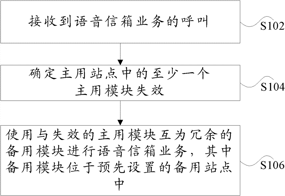
[0005] The present invention is proposed in view of the problem in the related art that when a module fails, the site containing the failed module is usually subjected to disaster recovery processing. Therefore, the main purpose of the present invention is to provide a disaster recovery method and device for voice mail services, to solve the above problems

Method used


Image

  • Disaster recovery method and device for voice mail service
  • Disaster recovery method and device for voice mail service
  • Disaster recovery method and device for voice mail service

Examples


Embodiment 1

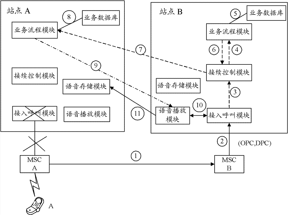
[0047] image 3 is a schematic diagram of disaster recovery for failure of an access call module according to an embodiment of the present invention, as shown in image 3 As shown, the following steps S301 to S311 are included.

[0048] In step S301, the access call module of the primary site fails, and the mobile call center automatically connects the call to the mobile call center connected to the backup site.

[0049] Step S302, the backup call center calls the backup access call module.

[0050] In step S303, the standby access call module still communicates with the connection control module in its own site.

[0051] In step S304, the backup site connection control module triggers the backup site service.

[0052] In step S305, the business process module of the standby site finds that the business process module of the main site is still in use, and accesses the service database to remove the position of the business process module of the main site.

[0053] In step ...

Embodiment 2

[0060] Figure 4 is a schematic diagram of disaster recovery for business process module failure according to an embodiment of the present invention, as shown in Figure 4 As shown, the following steps S401 to S409 are included.

[0061] Step S401, the main site user calls, and the main site access call module accesses.

[0062] Step S402, the main site access call module communicates with the main site connection control module.

[0063] In step S403, the connection control module of the primary site finds that the business process module fails, and the connection control module automatically switches to the standby business process module.

[0064] Step S404, the standby business process module finds the location of the main site business process module.

[0065] In step S405, the backup service process module detects that the service process module of the primary site fails, so the call will not be re-transferred to the primary site.

[0066] In step S406, the standby b...

Embodiment 3

[0071] Figure 5 It is a schematic diagram of the disaster recovery of the failure of the voice playback module according to the embodiment of the present invention, such as Figure 5 As shown, the following steps S501 to S509 are included.

[0072] In step S501, the connection control module of the primary site discovers that the voice playback module of the business process module adopts the 1+1 mode and can provide services for two sites at the same time. Calls made by users at the main site are accessed through the access call module at the main site.

[0073] Step S502, the main site access call module communicates with the main site connection control module.

[0074] In step S503, the main site connection control module communicates with the main site business process module.

[0075] Step S504, the main site business process module executes business logic.

[0076] In step S505, the business process module of the main site finds that the voice playback module fails...


PUM


Abstract

The invention discloses a disaster recovery method for voice mail service and a device adopting the same. The method comprises the following steps: receiving a call from the voice mail service; determining the failure of at least one principal module in a principal station; and adopting a standby module which is a redundancy to the failed principal module to achieve voice mail service, wherein the standby module is positioned in a standby station arranged in advance. By adopting the invention, the conventional resources are used to the maximum, and CAPEX (Capital Expenditure) and OPEX (Operating Expense) are reduced.

Description

technical field [0001] The present invention relates to the field of communications, in particular to a disaster recovery method and device for a voice mail service. Background technique [0002] The next generation communication network (NextGenerationNetwork, hereinafter referred to as NGN) is based on the softswitch, which can provide voice, data, video and multimedia services based on a comprehensive and open network architecture based on packet technology, which represents the development direction of the current communication network. [0003] Voice mail service is a very common service in NGN. This kind of service requires the following key modules to play a supporting role: the access call module that communicates with the core network MSC; the connection control module that controls the access call device to complete the call connection ; business process module for executing business processes; voice playback module for performing media playback, recording and numb...

Claims


Application Information

Patent Timeline
Patent Type & Authority Patents(China)
IPC IPC(8): H04L1/22H04L1/16H04L12/24
Inventor 戴立伟
Owner ZTE CORP
Learn More