
Gap coating valve and gap coating device

A gap and valve distribution technology, which is applied in the direction of valve device, device for coating liquid on the surface, valve operation/release device, etc., can solve problems such as uneven coating thickness, affecting coating quality, and easy blocking of slurry , to achieve the effect of improving coating uniformity, easy adjustment, and not easy to flow delay

Pending Publication Date: 2021-04-09
SUZHOU HYDROGINE POWER TECH CO LTD
View PDF0 Cites 0 Cited by
  • Summary
  • Abstract
  • Description
  • Claims
  • Application Information

AI Technical Summary

Problems solved by technology

After research, it is found that the existing valve structure for gap coating has the following disadvantages: when the valve port of the gap coating valve is opened, when the catalyst slurry passes through the valve port and flows to the position of the valve core, the slurry is easily blocked, and coating is easy to occur. The phenomenon of cloth delay makes the coating thickness uneven and affects the coating quality

Method used


Image

  • Gap coating valve and gap coating device
  • Gap coating valve and gap coating device
  • Gap coating valve and gap coating device

Examples


Embodiment Construction

[0031] In order to make the purpose, technical solutions and advantages of the embodiments of the present application clearer, the technical solutions in the embodiments of the present application will be described below in conjunction with the drawings in the embodiments of the present application.

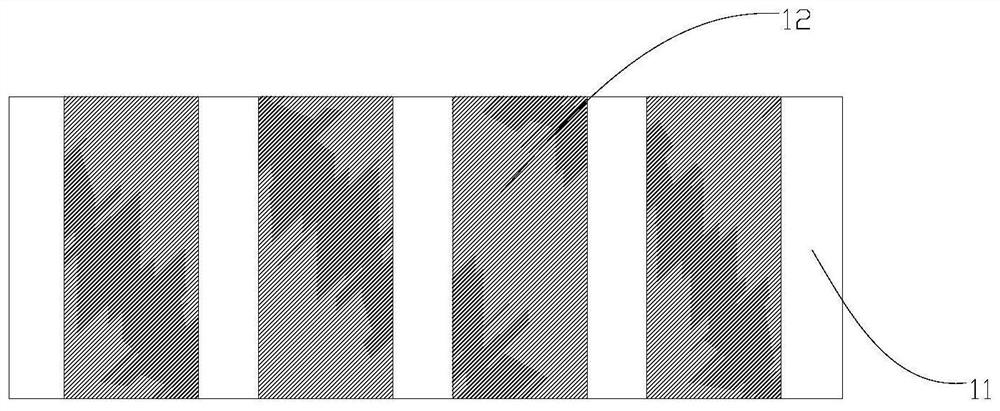
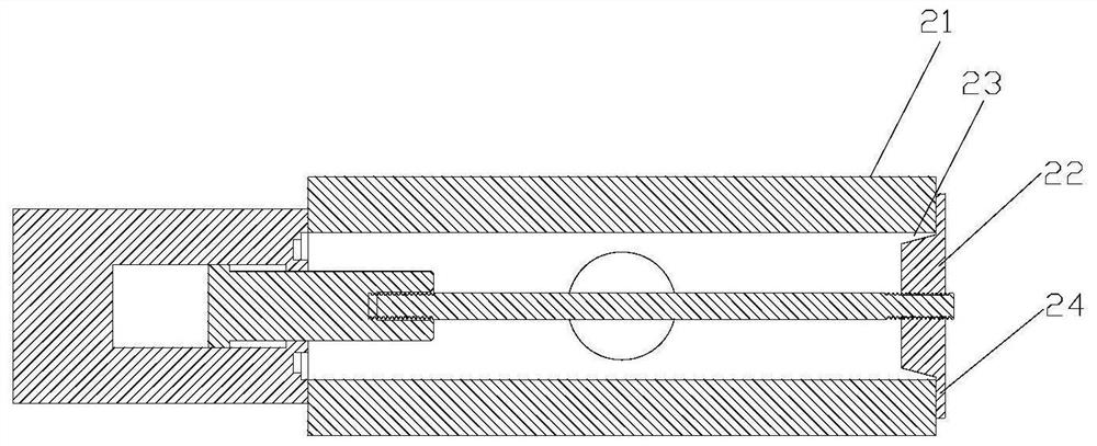
[0032] figure 2 It is a schematic cross-sectional structure diagram of a gap coating valve in the prior art. see figure 2 , the existing gap coating valve includes a valve core 22 and a valve body 21 that accommodates the valve core 22, the valve body 21 is provided with a valve port 23, and the valve core 22 slides relative to the valve body 21 in the direction of extension of the valve body 21 to Open or close valve port 23.

[0033] The spool 22 has a baffle 24. When the spool 22 closes the valve port 23 of the valve body 21, the plate surface of the baffle 24 is in sealing fit with the end surface where the valve port 23 is located, that is, when the spool 200 closes the ...


PUM


Abstract

The invention provides a gap coating valve and a gap coating device, and relates to the technical field of gap coating. The gap coating valve comprises a sleeve and a valve element, wherein the sleeve is provided with an inlet, an outlet and a flow channel communicating with the inlet and the outlet, the valve element is in sliding fit with the sleeve so that the valve element can be switched between a first position where the flow channel communicate and a second position where the flow channel is blocked, and when the valve element is positioned at the second position, the valve element and the sleeve are linear sealed. According to the gap coating valve, the valve is closed through linear sealing, so that the resistance borne by slurry when the slurry passes through the valve element can be reduced, the phenomenon that the slurry is blocked by the valve element is improved, the delay is reduced, coating is more uniform, and the coating quality is improved.

Description

technical field [0001] The present application relates to the technical field of gap coating, in particular, to a gap coating valve and a gap coating device. Background technique [0002] In the process of preparing the membrane electrode, the catalyst layer is usually gap-coated on the proton membrane, and then the coated proton membrane coil is cut to prepare the membrane electrode. figure 1 It is a structural schematic diagram of the proton membrane coated with a catalyst layer in the prior art. see figure 1 , gap-coating the catalyst layer 12 on the proton membrane 11 (or other protective membranes), and then cutting the proton membrane 11 at the region of the proton membrane 11 not coated with the catalyst layer 12, so as to prepare the membrane electrode. [0003] At present, in order to realize the gap coating on the proton membrane, the gap coating is realized by controlling the valve core of the gap coating valve in the gap coating device to intermittently open an...

Claims


Application Information

Patent Timeline
Patent Type & Authority Applications(China)
IPC IPC(8): F16K1/00F16K1/38F16K27/02F16K31/122B05C5/02
CPCB05B12/00F16K1/00F16K1/38F16K27/0254F16K31/122
Inventor 江朝磊乔静王秀王春梅吴丹朱威
Owner SUZHOU HYDROGINE POWER TECH CO LTD
Learn More