Digital pre-distortion processing system with sample rate conversion and method thereof
A digital predistortion and processing system technology, applied in digital transmission systems, baseband systems, transmission systems, etc., can solve problems such as poor predistortion effect, poor digital predistortion processing method, and inaccurate predistortion function.
- Summary
- Abstract
- Description
- Claims
- Application Information
AI Technical Summary
Problems solved by technology
Method used
Image
Examples
Embodiment 1
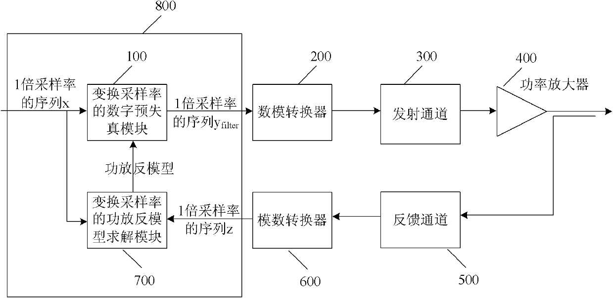
[0083] figure 1 A schematic composition diagram of a digital pre-distortion processing system for converting a sampling rate according to an embodiment of the present invention is shown. The digital pre-distortion processing system 800 for changing the sampling rate in this embodiment is mainly composed of a power amplifier inverse model solution module 700 for changing the sampling rate and a digital pre-distortion module 100 for changing the sampling rate.
[0084] The complex number sequence x of 1 times the sampling rate is first sent to the digital pre-distortion module 100 that converts the sampling rate, and the output sequence y of 1 times the sampling rate filter , after passing through the digital-to-analog converter 200 and the transmitting channel 300 successively, it is sent to the power amplifier 400 . A part of the power of the RF signal output by the power amplifier 400 is coupled to the feedback channel 500, and the sequence z is obtained after passing throug...
Embodiment 2
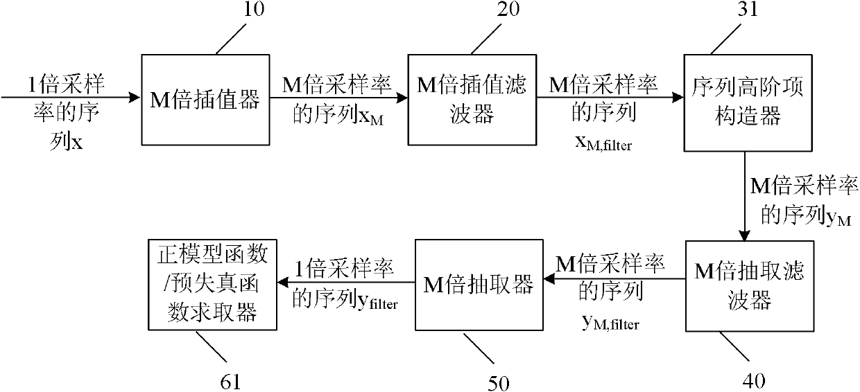
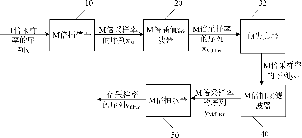
[0090] Figure 4 A schematic composition diagram of a power amplifier inverse model solution module 700 for converting a sampling rate according to another embodiment of the present invention is shown. The main difference between this embodiment and the foregoing embodiments is that the M-fold upsampling device is an integral module. Will figure 2 The M times interpolator 10 and the M times interpolation filter 20 are combined into M times interpolation and M times interpolation filter 70, and then M times decimation filter 40 and M times decimator 50 are combined into M times decimation filter and M times The extractor 80 can obtain this embodiment.
[0091] The sequence x of 1 times the sampling rate is first sent to the M times interpolation and the M times interpolation filter 70, and the sequence x of the output M times the sampling rate M,filter Send it to the sequence high-order item constructor 31, and output the sequence y of M times the sampling rate M Send to M...
Embodiment 3
[0095] Image 6 A schematic composition diagram of a sample rate converted power amplifier inverse model solving module 700 according to another embodiment of the present invention is shown. Will Figure 4 M times of interpolation and M times of interpolation filter 70 are replaced by M times of interpolation polyphase filter 70 with M branches 1 、70 2 ...70 M , then replace the M-fold decimation filter and the M-fold decimator 80 with an M-fold decimation polyphase filter 80 with M branches 1 , 80 2 ...80 M , and then copy the sequence high-order item constructor 31 into M sequence high-order item constructors 31 1 、31 2 ...31 M (place a sequence high-order item constructor 31 on each branch i of the polyphase filter i ), this embodiment can be obtained.
[0096] The sequence x of 1 times the sampling rate is first sent to the M times interpolation polyphase filter 70 with M branches 1 、70 2 ...70 M , respectively output the sequence x of 1 times the sampling rat...
PUM
 Abstract
Description
Claims
Application Information
 - R&D
- Intellectual Property
- Life Sciences
- Materials
- Tech Scout
- Unparalleled Data Quality
- Higher Quality Content
- 60% Fewer Hallucinations
Browse by: Latest US Patents, China's latest patents, Technical Efficacy Thesaurus, Application Domain, Technology Topic, Popular Technical Reports.
© 2025 PatSnap. All rights reserved.Legal|Privacy policy|Modern Slavery Act Transparency Statement|Sitemap|About US| Contact US: help@patsnap.com


