Aircraft throttle control device including a cam coupling

A control device, cam technology, applied in mechanical control devices, aircraft power units, control components, etc., can solve the problems of redundancy, increase the weight and volume of the clutch system, etc.

Active Publication Date: 2012-07-11
SAGEM DEFENSE SECURITE SA
View PDF8 Cites 10 Cited by
  • Summary
  • Abstract
  • Description
  • Claims
  • Application Information

AI Technical Summary

Problems solved by technology

In addition, the large forces transmitted require proper dimensioning of the parts of the clutch system, thereby increasing the weight and volume of the clutch system, especially since any element in the clutch system between any lever and the code disc must be double to ensure the redundancy necessary for the safety of the device

Method used


Image

  • Aircraft throttle control device including a cam coupling
  • Aircraft throttle control device including a cam coupling
  • Aircraft throttle control device including a cam coupling

Examples


Embodiment Construction

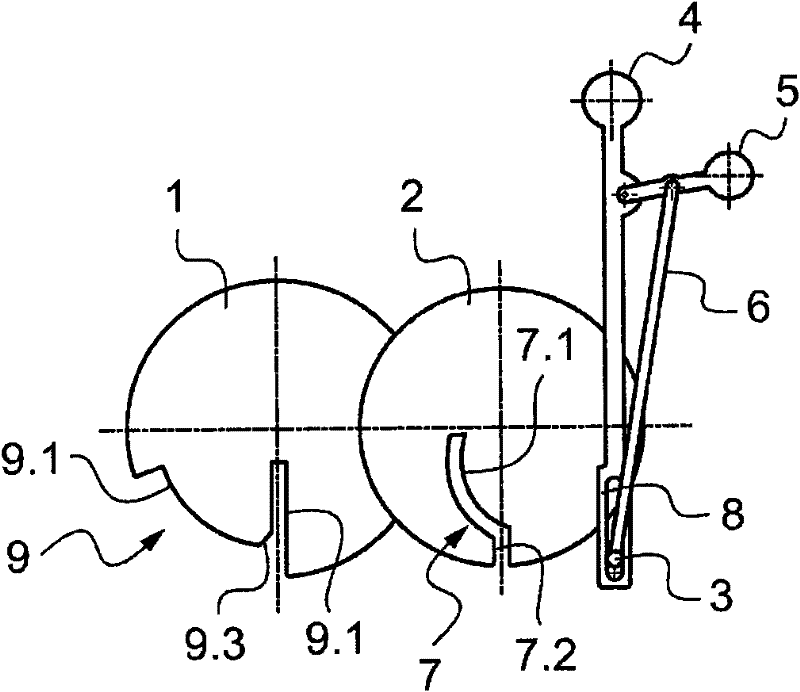
[0029] The throttle control device described herein is arranged to control the fuel flow rate and thrust reversal device of an aeroengine.

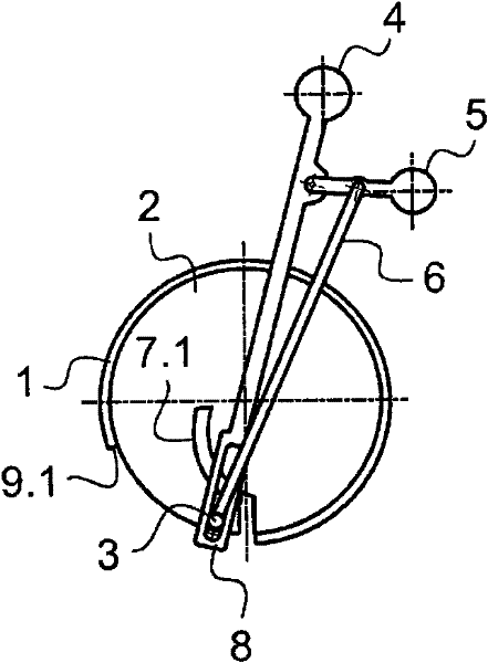
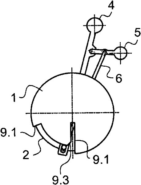
[0030] refer to Figures 1 to 5 , the control device includes a mounting frame 1 having a code disc 2 pivotally mounted thereon. A sensor (not shown) for detecting the angular position of the code disc 2 is mounted on the mounting frame 1 and aligned with the outline of the code disc 2 .

[0031] The main joystick 4 is mounted on the mount 1 to pivot about the same axis as the code wheel 2 . The primary joystick 4 has a radially offset structure, on which the secondary joystick 5 is mounted to pivot about an axis parallel to the axes of rotation of the code disc 2 and the primary joystick 4 . Joysticks 4 and 5 are in rest positions ( figure 1 The two joysticks are shown in ) and pivot between the maximum actuated position. The main joystick 4 is the throttle control joystick used to control the fuel flow rate, and its maximum actuatio...


PUM


Abstract

The invention relates to an aircraft engine control device comprising a frame (1) having the following elements pivotally mounted thereon, namely: a thumb wheel (2), and a main lever (4) and a secondary lever (5) for rotating the thumb wheel, whereby each lever can move between a rest position and a maximum actuation position, said secondary lever being mounted to pivot on the main lever. Cam channels (7) are provided on the thumb wheel and the frame, such that the main lever can drive the thumb wheel when the main lever is moved from the rest position of the secondary lever, and the secondary lever can drive the thumb wheel when the secondary lever is moved from the rest position of the main lever, the movement of one lever being prevented when the other lever is not in the rest position.

Description

technical field [0001] The invention relates to a throttle control device for an aero-engine. Background technique [0002] Modern turbojets are equipped with thrust reversal devices which direct a portion of the exhaust flow leaving the turbojet in front of the turbojet (usually at an angle of about 45° relative to the direction the aircraft is heading) so that The slowing action of the auxiliary brakes when the aircraft is landing. Various thrust reversal devices exist, in particular those using doors and those using grids. [0003] There are also propeller engines comprising thrust reversing means arranged to reverse the pitch of the propeller. [0004] The cockpit of an aircraft having such an engine is equipped with a throttle control which enables the pilot to control the rate at which fuel is admitted into the combustion chamber of the engine and also controls the thrust reverser. For this purpose, the control unit comprises a mounting bracket having a code wheel p...

Claims


Application Information

Patent Timeline
Patent Type & Authority Applications(China)
IPC IPC(8): B64D31/04G05G1/04B63H21/22
CPCB64D31/04
Inventor H·伊拉贝罗伊J-E·贝索德S·保塔德T·卡特瑞D·英格勒E·莫勒迪
Owner SAGEM DEFENSE SECURITE SA
Why Eureka
Try Eureka