Exhaust purification device of internal combustion engine

An exhaust gas purification device and a technology for an internal combustion engine, which are applied in the direction of the exhaust device, the electronic control of the exhaust gas treatment device, the diagnosis device of the exhaust gas treatment device, etc., can solve the problems such as the decrease of the purification ability

Inactive Publication Date: 2012-07-11
TOYOTA JIDOSHA KK
View PDF7 Cites 0 Cited by
  • Summary
  • Abstract
  • Description
  • Claims
  • Application Information

AI Technical Summary

Problems solved by technology

When the temperature of the catalyst deviates from this active temperature range, the purification ability drops significantly

Method used


Image

  • Exhaust purification device of internal combustion engine
  • Exhaust purification device of internal combustion engine
  • Exhaust purification device of internal combustion engine

Examples


Embodiment Construction

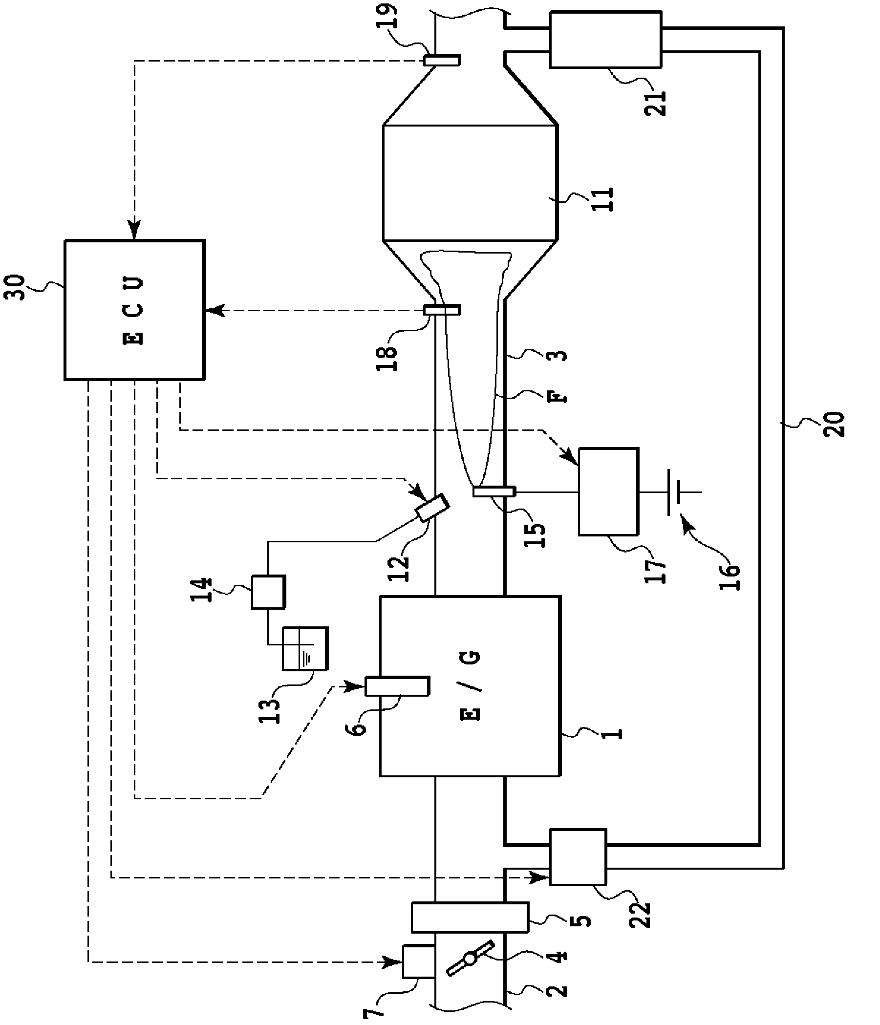
[0025] Embodiments of the present invention will be described below. exist figure 1 Among them, the exhaust gas purification device of an internal combustion engine according to the first embodiment has an engine 1 , an intake pipe 2 and an exhaust pipe 3 . The engine 1 is a diesel internal combustion engine, but may also be other types of internal combustion engines.

[0026] A throttle valve 4 and a surge tank 5 are arranged in the intake pipe 2 . The throttle valve 4 is driven by a throttle valve actuator 7 . The travel injector 6 is provided toward the combustion chamber of the engine 1 .

[0027] Exhaust pipe 3 in figure 1 The left side in the figure is the upstream side and is connected to the engine 1 , and the right side in the figure is the downstream side and is connected to a muffler not shown. A catalyst 11 is provided in the exhaust pipe 3 . The catalyst 11 is composed of, for example, an oxidation catalyst, a three-way catalyst, or a NOx catalyst, and cordi...


PUM


Abstract

Disclosed is an exhaust purification device of an internal combustion engine, wherein deterioration of an ignition means due to burning of a foreign substance adhered to the ignition means is suppressed. Specifically disclosed is an exhaust purification device of an internal combustion engine, which comprises a fuel supply device (12) for supplying fuel into an exhaust passage (3) of an internal combustion engine, a heating device (15) for burning the supplied fuel, and a controller (30). When an unburnt combustible component of exhaust is deposited on the heating device (15), the controller (30) makes the heating device (15) burn and remove the deposited unburnt combustible component before increasing the temperature of the exhaust by igniting the fuel, which is supplied from the fuel supply device (12), by means of the heating device (15).

Description

technical field [0001] The present invention relates to an exhaust purification device having a function of supplying fuel to an exhaust passage of an internal combustion engine. Background technique [0002] A catalyst provided in an exhaust passage of an internal combustion engine has an active temperature range suitable for purification of harmful components. When the temperature of the catalyst deviates from this active temperature range, the purification ability drops significantly. [0003] In the device disclosed in Patent Document 1, for the purpose of activating the catalyst, an addition valve for injecting fuel and an ignition unit for igniting the injected fuel are provided upstream of the catalyst in the exhaust passage. When the temperature of the catalyst is lower than the activation temperature, the fuel supplied from the addition valve is ignited by the ignition means, thereby raising the temperature of the catalyst. [0004] prior art literature [0005] ...

Claims


Application Information

Patent Timeline
Patent Type & Authority Applications(China)
IPC IPC(8): F01N3/20F01N3/02F01N3/38
CPCF01N9/00F01N2550/00F01N2610/03F01N3/36Y02T10/47F01N2240/14Y02T10/20Y02T10/12Y02T10/40
Inventor 辻本健一
Owner TOYOTA JIDOSHA KK
Why Eureka
Try Eureka