
Cooling system, in particular for a motor vehicle

A technology for cooling systems and motor vehicles, which is applied in engine cooling, coolant flow control, machine/engine, etc., and can solve problems such as shortening the thermal cycle stage and reducing the cooling power of the cooling medium pump

Inactive Publication Date: 2012-07-11
VOITH PATENT GMBH
View PDF6 Cites 4 Cited by
  • Summary
  • Abstract
  • Description
  • Claims
  • Application Information

AI Technical Summary

Problems solved by technology

[0004] Although the last-mentioned embodiment achieves an adaptation of the power absorbed by the coolant pump to the cooling power required in the current motor vehicle and thus leads to fuel savings, it also consists in the fact that the operating medium and cooling of the fluid coupling The cooling medium of the circulation circuit is the same, and the thermal cycle phase can be shortened by reducing the cooling power of the cooling medium pump during the cold start of the drive, but using a conventional hydraulic coupling in the transmission line between the drive unit and the cooling medium pump problems arise when emptying the working chamber of the turbo coupling in order to partially or completely disconnect the coolant pump

Method used


Image

  • Cooling system, in particular for a motor vehicle
  • Cooling system, in particular for a motor vehicle
  • Cooling system, in particular for a motor vehicle

Examples


Embodiment Construction

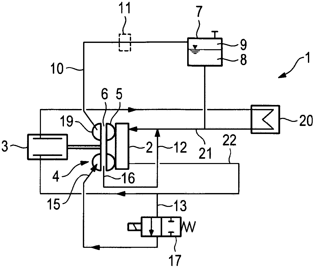
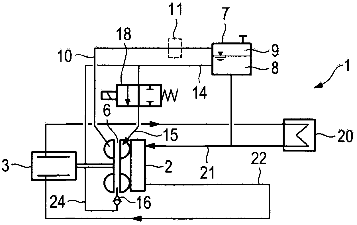
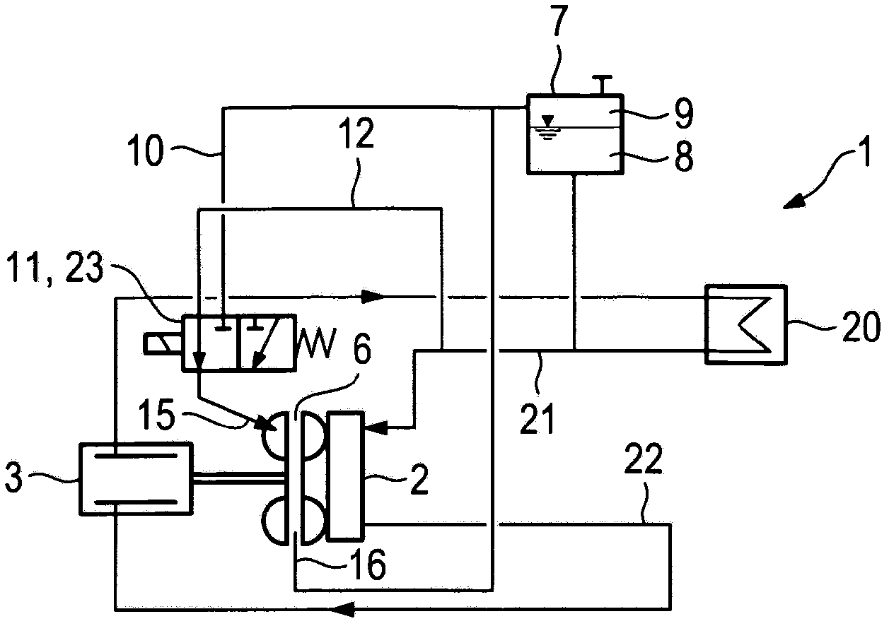
[0028] exist Figure 1 to Figure 6 All figures show schematically a cooling system with a cooling circuit 1 in which a coolant pump 2 is driven by means of a drive 3 via a hydraulic coupling 4 , wherein the hydraulic coupling 4 The turbine 5 is hydraulically driven by the working medium circulation circuit in the working chamber 6 and is driven by the pump impeller 19 , which is designed in one piece with the impeller of the coolant pump 2 . The drive unit 3 is cooled by means of a cooling medium, and the heat from the cooling medium is dissipated to the surroundings by means of a heat exchanger 20 . The cooling medium is simultaneously the working medium of the fluid coupling 4 .

[0029] The coolant pump 2 pumps coolant from the suction side 21 to the pressure side 22 . according to Figures 1 to 4 In the embodiment, the compensation container 7 is connected to the suction side 21 in a cooling medium-conducting manner / in a working medium-conducting manner. On the contrar...


PUM


Abstract

The invention relates to a cooling system, in particular a motor vehicle cooling system, having a cooling circuit in which a cooling medium is circulated by means of a cooling medium pump; the cooling medium pump or another work machine being driven by means of a drive machine via a hydrodynamic coupling, comprising a pump impeller driven by the drive machine and a turbine wheel driven by the cooling medium pump, which together form a toroidal working chamber that can optionally be filled with working medium; the working medium being the cooling medium; having a compensating container, comprising a space filled with cooling medium and an air chamber above a cooling medium level in the chamber filled with the cooling medium. The invention is characterized in that the working chamber of the hydrodynamic coupling is always connected to the air chamber or can optionally be connected to the latter via an air-conducting connection.

Description

technical field [0001] The invention relates to a cooling system in particular according to the features in the preamble of claim 1 . Background technique [0002] Such a cooling system serves to cool a drive engine and / or other combined units, in particular a drive train of a motor vehicle. The cooling system includes a cooling circuit in which a cooling medium is circulated by means of a cooling medium pump. The cooling medium is, for example, water or a mixture of water. By circulating in the cooling circuit, the cooling medium is conveyed to the combined unit to be cooled, in particular the drive motor, where it absorbs the heat to be released and then continues to the heat exchanger arranged in the cooling circuit, in particular Water-air-heat exchanger, where the heat exchanger releases the absorbed heat to the surrounding environment. In principle, the heat absorbed by the cooling medium is also not simply dissipated to the surroundings, but is used in the drive tr...

Claims


Application Information

Patent Timeline
IPC IPC(8): F01P5/12F01P11/02F16D35/02F01P7/16
CPCF01P5/12F01P11/029F01P7/164F16D33/16F01P11/02F16D35/02F01P7/16
Inventor 桑德拉·巴特尔马埃斯约亨·特尼森马库斯·克莱迪特尔·劳克曼
Owner VOITH PATENT GMBH
Learn More