
Impeller of aerator and aerator equipped with impeller

An aerator and impeller technology, applied in mechanical equipment, machines/engines, liquid fuel engines, etc., can solve problems such as death, injury, fish and shrimp stuck in the window, etc., to improve oxygenation capacity and reduce complexity Effect

Inactive Publication Date: 2014-01-15
吴为国
View PDF11 Cites 0 Cited by
  • Summary
  • Abstract
  • Description
  • Claims
  • Application Information

AI Technical Summary

Problems solved by technology

The impeller of the impeller type aerator has metal welded impeller and plastic impeller. Most of the plastic impellers are assembled, and there are also integral injection molded impellers such as patent number: 201010183031.7. A window is set under the lower support plate of the impeller to make the mold structure simple. For implementation, the water body in the cone can flow outward through the window, increase the water body exchange capacity, and improve the efficiency of oxygenation, but the disadvantage is that fish and shrimp are easy to get stuck in the window, causing injury or death

Method used


Image

  • Impeller of aerator and aerator equipped with impeller
  • Impeller of aerator and aerator equipped with impeller
  • Impeller of aerator and aerator equipped with impeller

Examples


Embodiment Construction

[0031] The present invention will be further described below with specific embodiments in conjunction with the drawings, see Figure 1-11 :

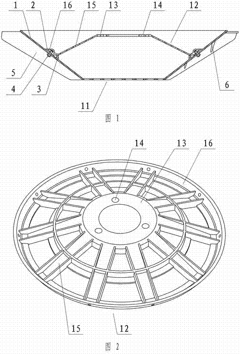
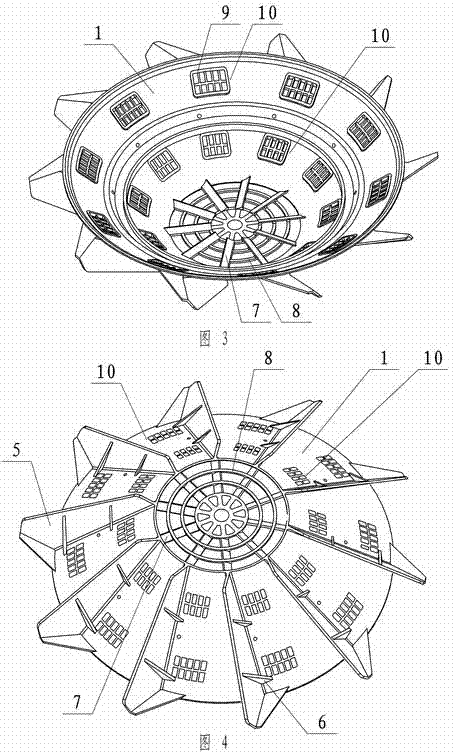
[0032] An impeller of an aerator, which is mainly composed of a cone 1, a blade 5, a connecting disc 12, etc. The cone 1 and a plurality of blades 5 are integrally molded by injection molding, and the cone 1 is a cone shell with a large upper and a smaller lower. There is a filter screen 11 on the small end; there are multiple water-passing windows 10 on the cone 1 and a grid in the window 10, which is set on the back of the blade; the connecting disc 12 and the cone 1 are firmly connected, and the middle of the connecting disc 12 There is a mounting position 13 and a mounting hole 14 connected to the aerator, and a water passage is provided on the connecting plate 12.

[0033] The filter screen 11 at the small end of the cone and the cone 1 are injection molded together. The main rib 7 and the ring-shaped secondary rib 8 form the filter scr...


PUM


Abstract

The invention relates to an impeller of an aerator and an aerator equipped with the impeller. The impeller is mainly composed of a conical body, blades and a connecting plate and so on. The conical body and a plurality of blades are integrally formed by injection. The conical body is a conical shell with a larger upper part and a smaller lower part. A filter net is arranged at the small end of the conical body. A plurality of windows for passing through water are arranged on the conical body. The connecting plate is tightly connected with the conical body. An installing position and an installing hole which are connected with the aerator are arranged in the middle part of the connecting plate. A motor is connected with a reduction box. The output shaft of the reduction box is connected with the impeller by a flange to drive the impeller to rotate. The reduction box is mainly composed of a box body, an upper cover, a secondary reduction gear, a bearing and an output shaft. One end of a supporting rod is installed in a circular hole, wherein the circular hole is composed of the upper cover, an upper semicircular groove and a lower semicircular groove of the box body. A fixed ring is arranged at the other end of the supporting rod. The fixed ring is connected with a floating body to float the aerator on water surface. The whole impeller is changed into a conical body and the conical body and the blade are integrally formed by injection. Meanwhile, the filter net and a window grate are molded by injection, and the connecting plate is independently molded by injection, so that the complexity of the die is reduced to effectively prevent fish and shrimps from being stuck in the windows.

Description

technical field [0001] The invention relates to an aerator, in particular to an aerator with a filter impeller, which belongs to fish farming machinery. Background technique [0002] The aerator is a life-saving and stimulating equipment for fish and shrimp in aquaculture. Existing mechanical aerators mainly include three types: water wheel type, impeller type and water spray type, among which the impeller type aerator is the most widely used. The impeller of the impeller type aerator has metal welded impeller and plastic impeller. Most of the plastic impellers are assembled, and there are also integral injection molded impellers such as patent number: 201010183031.7. A window is set under the lower support plate of the impeller to make the mold structure simple. For implementation, the water body in the cone can flow outward through the window, increase the water body exchange capacity, and improve the efficiency of oxygenation, but the unfavorable consequence is that fis...

Claims


Application Information

Patent Timeline
Patent Type & Authority Patents(China)
IPC IPC(8): A01K63/04A01K61/00F04D29/18C02F7/00
CPCY02A40/81Y02W10/10
Inventor 吴为国
Owner 吴为国
Learn More