Internal spiral evaporator

A technology of evaporator and inner spiral tube, which is applied in the fields of electronics and photovoltaics, can solve the problems of reduced production efficiency, reduced batch output, and affecting the reaction process, and achieves the effect of less equipment investment and quick results

Active Publication Date: 2014-01-01
NANJING ARGOTECH NEW ENERGY MATERIALS
View PDF5 Cites 0 Cited by
  • Summary
  • Abstract
  • Description
  • Claims
  • Application Information

AI Technical Summary

Problems solved by technology

[0003] However, this technical solution has a disadvantage, that is, during the drying process, a large amount of ammonium chloride is adsorbed on the inner wall of the evaporator, with a thickness of 3-5MM, which seriously affects the entire reaction process, making the drying time far longer than the reaction time and reducing production efficiency. Greatly reduced, the batch output per unit time is reduced

Method used


Image

  • Internal spiral evaporator

Examples


Embodiment Construction

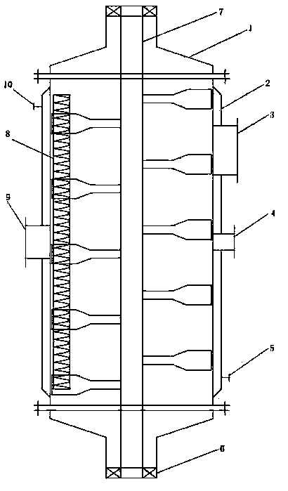
[0013] The present invention will be further described below in conjunction with accompanying drawing and specific embodiment:

[0014] Such as figure 1 Shown: an internal spiral evaporator, including evaporator cylinder 1, jacket 2, manhole 3, feed inlet 4, steam inlet 5, mechanical seal 6, agitator 7, internal spiral pipe 8, and discharge port 9 and a steam outlet 10, the evaporator cylinder 1 is provided with a jacket 2, and the manhole 3, the feed port 4, and the discharge port 9 respectively pass through the jacket 2 and are fixedly connected to the evaporator cylinder 1, The lower part of the jacket 2 is provided with a steam inlet 5, the upper part of the jacket 2 is provided with a steam outlet 10, and the evaporator cylinder 1 is provided with an agitator 7, and the agitator 7 and the upper and lower outlets of the evaporator cylinder 1 A mechanical seal 6 is provided between them, and an inner spiral tube 8 is placed inside the evaporator cylinder 1 . The inner hel...


PUM


Abstract

The invention discloses an internal spiral evaporator, which comprises an evaporator cylinder, a clamping sleeve, a manhole, a feed inlet, a steam inlet, mechanical seals, a stirrer, an internal spiral pipe, a feed outlet and a steam outlet, wherein the evaporator cylinder is externally provided with the clamping sleeve, the manhole, the feed inlet and the feed outlet respectively penetrate through the clamping sleeve to be fixedly connected with the evaporator cylinder, the lower part of the clamping sleeve is provided with the steam inlet, the upper part of the clamping sleeve is provided with the steam outlet, the evaporator cylinder is internally provided with the stirrer, the mechanical seals are arranged between the stirrer and an upper outlet of the evaporator cylinder, as well as between the stirrer and a lower outlet of the evaporator cylinder, and the evaporator cylinder is internally provided with the internal spiral pipe. According to the invention, the internal spiral pipe is additionally arranged on the basis of the original evaporator, the equipment investment is less, the effect is fast, the entire drying process is enhanced by 80% on the original basis, the output of the each batch at the unit time is enhanced more than 80%, and zero release is achieved during the whole production process.

Description

technical field [0001] The invention relates to the fields of electronics and photovoltaics, in particular to an evaporation device in the production process of silane. Background technique [0002] The production process of silane produced by the Komatsu method, at the end of the whole production process, will produce a solid-liquid mixture composed of liquid ammonia and ammonium chloride, in which the liquid ammonia can be recycled and reused, and the ammonium chloride can be used as fertilizer to make the whole production The process achieves zero emissions. The common technical solution is to put the mixture of liquid ammonia and ammonium chloride into the evaporator, and then pass steam into the jacket of the evaporator to heat, so as to vaporize the liquid ammonia and separate the solid ammonium chloride. Usually the steam pressure is controlled at 0.3-0.5MPa, the temperature in the evaporator is controlled at 100-150°C, and the entire vaporization and separation proc...

Claims


Application Information

Patent Timeline
Patent Type & Authority Patents(China)
IPC IPC(8): B01D1/00
Inventor 徐昕郑春宁尤向东何波
Owner NANJING ARGOTECH NEW ENERGY MATERIALS
Why Eureka
Try Eureka