Dust removal device

A technology of dust removal device and box, which is applied in combination devices, dispersed particle separation, chemical instruments and methods, etc., can solve the problems of easy clogging of the filter layer, large working resistance, inconvenient management, etc., and achieves light weight and reduces maintenance frequency. , the effect of easy maintenance

Inactive Publication Date: 2012-07-18
SANY HEAVY EQUIP
View PDF7 Cites 13 Cited by
  • Summary
  • Abstract
  • Description
  • Claims
  • Application Information

AI Technical Summary

Problems solved by technology

[0004] The dust removal device in the prior art has large working resistance and high energy consumption; when the dust concentration is high, the filte

Method used


Image

  • Dust removal device
  • Dust removal device
  • Dust removal device

Examples


Embodiment 1

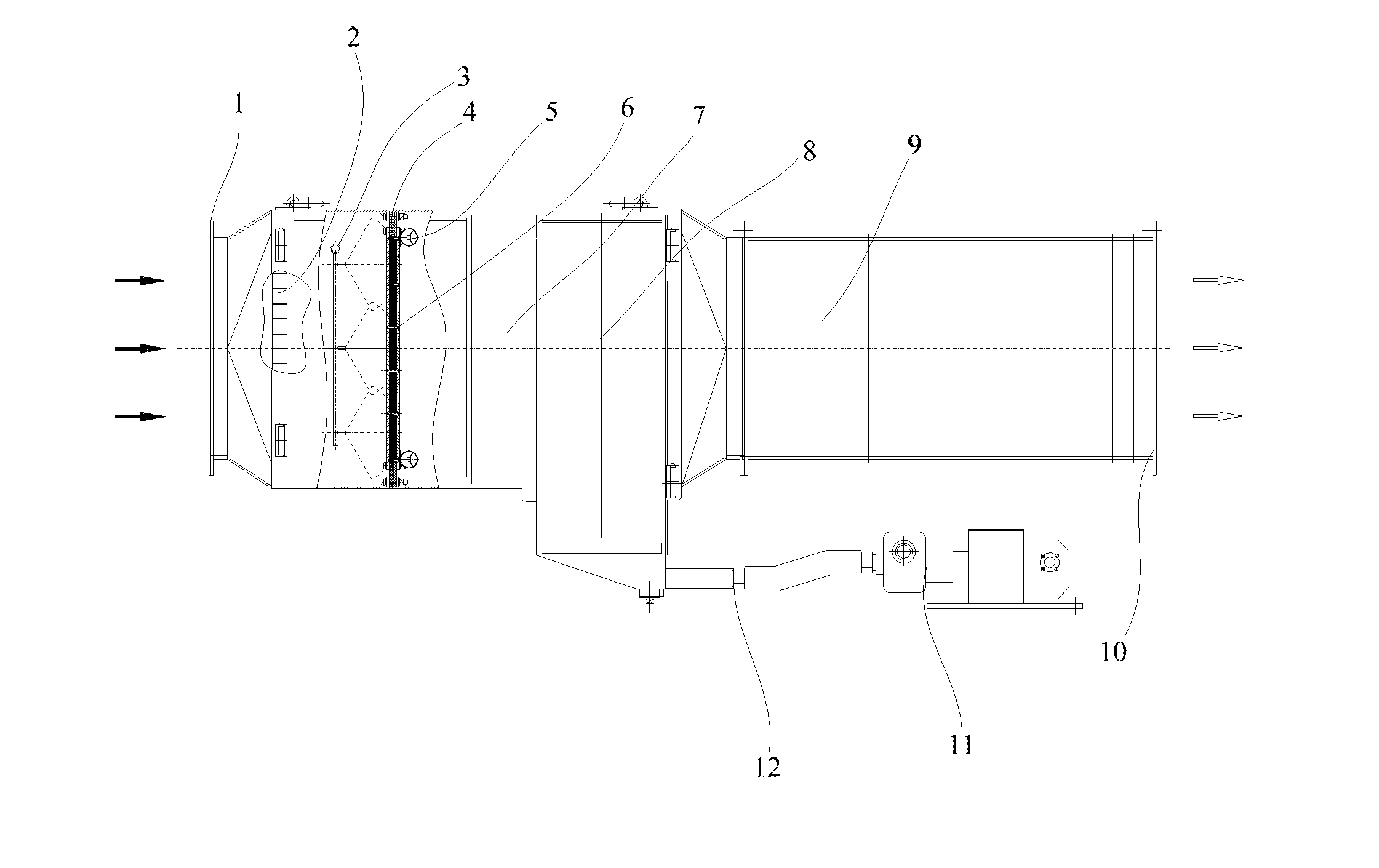
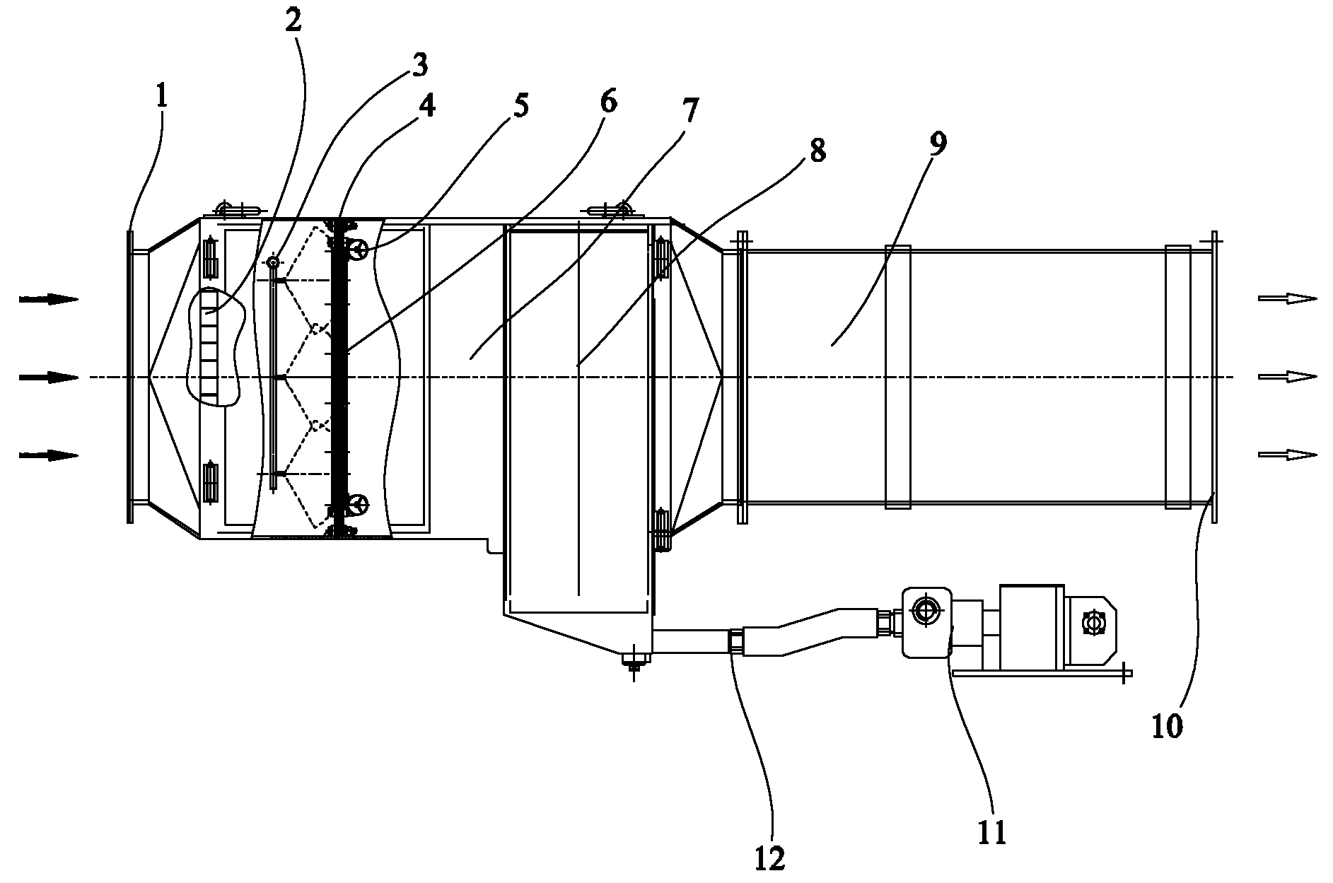
[0023] figure 1 A schematic structural view of a dust removal device according to an embodiment of the present invention is shown.

[0024] One embodiment of the present invention provides a dust removal device, such as figure 1 As shown, it includes a dust removal box 7 placed horizontally. The inner cavity of the dust removal box 7 is a gas flow channel. One end of the dust removal box 7 is provided with an air inlet 1, and the other end is connected to a fan 9. The rear of the fan is It is an air outlet 10, and some nozzles 3 for spraying water are arranged in the dust removal box 7, and a filter layer 6 is arranged behind the nozzle 3, and a vibration motor 5 is installed at the rear of the filter layer. After 6, a dehydrator 8 is arranged. In this embodiment, the fan can be an axial fan, a centrifugal fan, or other fans; the vibration motor can be one or more, so as to achieve the vibration effect that best meets the actual needs. should. In this technical solution, s...

Embodiment 2

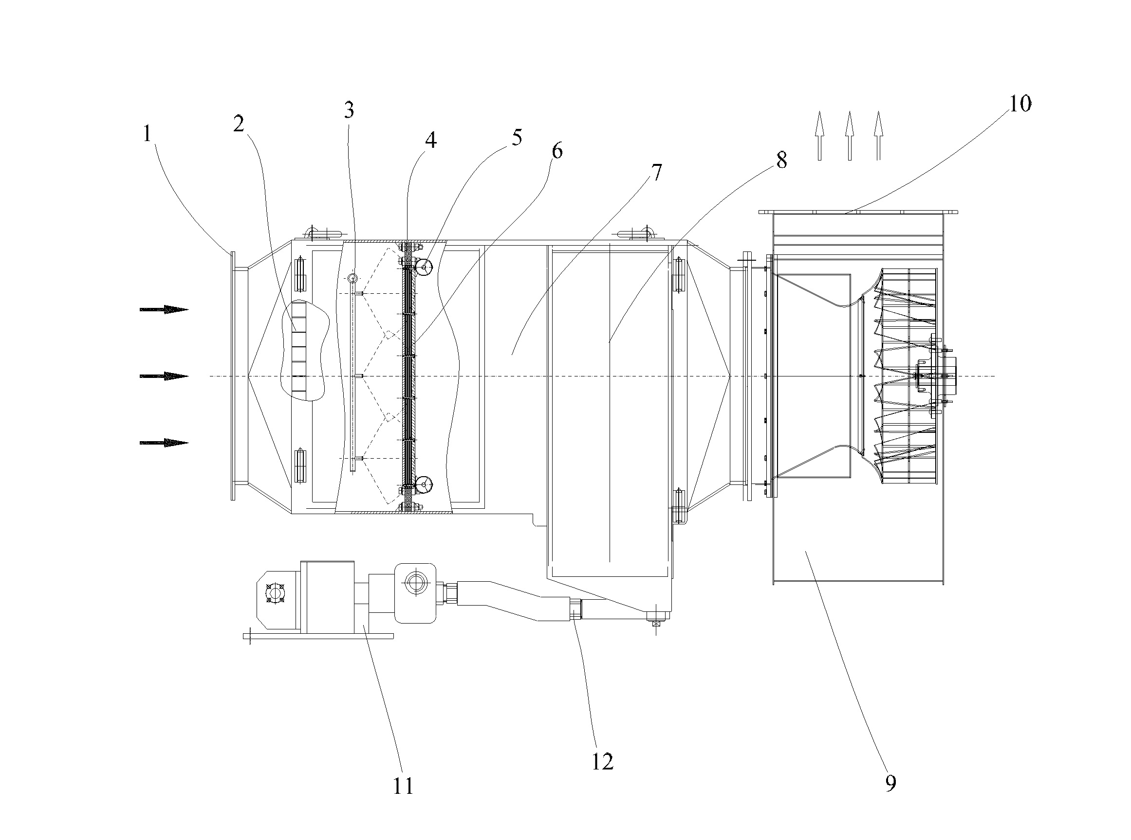
[0035] figure 2 A schematic structural view of a dust removal device according to another embodiment of the present invention is shown.

[0036] like figure 2 As shown, in this embodiment, the difference from that in Embodiment 1 is that the fan 9 is a centrifugal fan, and the inlet of the centrifugal fan 9 is provided with a collector.

[0037] like figure 2 As shown, in the above technical solution, optionally, a second protective lining is provided between the impeller of the centrifugal fan 9 and the collector, and the second protective lining is processed by copper or plastic. The inlet of the centrifugal fan is provided with a collector, and a second protective lining is provided between the impeller of the centrifugal fan and the collector, and the second protective lining is made of copper or plastic, so that the impeller and the collector The sparks produced by the impact of the protective lining meet the safety performance requirements of the friction spark tes...


PUM


Abstract

The invention provides a dust removal device, which comprises a horizontally arranged dust removal box body, wherein an inner cavity of the dust removal box body is a gas flow channel; an air inlet is formed at one end of the dust removal box body, and the other end of the dust removal box body is connected with a fan; an air outlet is formed on the rear part of the fan; a plurality of water sprayers are arranged in the dust removal box body; a filter layer is arranged behind the sprayers; a vibration motor is arranged on the rear part of the filter layer; and a labyrinth-type dehydrator is arranged behind the filter layer. According to the dust removal device, dust in the air is stopped effectively, and an effect of purifying the air is achieved; water-containing dust is removed from the filter layer through the vibration of the vibration motor, so that further self-purification of the filter layer is realized, the probability that the filter layer is blocked is reduced greatly, and the maintenance frequency is reduced; and the dust removal device has a small volume, light weight, high dust removal efficiency, a simple structure, long service life and low energy consumption, is convenient to maintain, safe and reliable, and meets demands for ventilation, dust extraction and dust-containing air purification on working surfaces or other dust production working sites of coal mine underground tunnellers.

Description

technical field [0001] The invention relates to a dust removal device, more specifically, to a dust removal device with self-purification function. Background technique [0002] In related technologies, most dust collectors with vibration are bag-type dry dust collectors. Bag-type dust collectors must rely on vibration to remove dust particles from the inner wall of the filter and filter bags. There is also a water-bath dust collector. The flue gas or dust dives into the water for absorption, and the water in the water tank is the one that vibrates, just to make the dust fully absorbed by the water. [0003] The wet dust removal device in the prior art generally includes a dust removal box placed horizontally. One end of the box is provided with an air inlet, and the other end of the box is connected to a fan. The rear of the fan is an air outlet. The nozzle is used to moisten and capture dry dust. There is a filter layer behind the nozzle. When the fan rotates and draws th...

Claims


Application Information

Patent Timeline
IPC IPC(8): B01D50/00
Inventor 黄向阳杨素玲秦宇曹春雨宋佩玉
Owner SANY HEAVY EQUIP
Why Eureka
Try Eureka