Soldering set for agitating friction welding with adjustable inclined angle and concave-top and convex-bottom type shaft shoulder and method thereof

A friction stir welding and shaft shoulder technology, applied in the field of friction stir welding welding tools, can solve the problems of difficulty in forming the weld, reduced joint performance, excessive heat input, etc., to ensure that the upper surface is formed, well formed, simplified The effect of the operation

Active Publication Date: 2012-07-18
安徽万宇机械设备科技有限公司
View PDF5 Cites 13 Cited by
  • Summary
  • Abstract
  • Description
  • Claims
  • Application Information

AI Technical Summary

Problems solved by technology

[0003] The purpose of the present invention is to solve the problem that the existing dual-shaft shoulder self-sustaining friction stir welding requires prefabricated guide holes and outlet holes, the heat input in the friction stir welding process is too large to reduce the performance of the joint and the condition of no rigid backing plate support To solve the problem that the weld seam is difficult to form, a welding tool and method for friction stir welding with adjustable inclination angle and concave and convex shoulders are provided

Method used


Image

  • Soldering set for agitating friction welding with adjustable inclined angle and concave-top and convex-bottom type shaft shoulder and method thereof
  • Soldering set for agitating friction welding with adjustable inclined angle and concave-top and convex-bottom type shaft shoulder and method thereof
  • Soldering set for agitating friction welding with adjustable inclined angle and concave-top and convex-bottom type shaft shoulder and method thereof

Examples


specific Embodiment approach 1

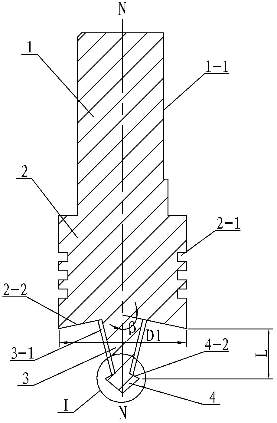
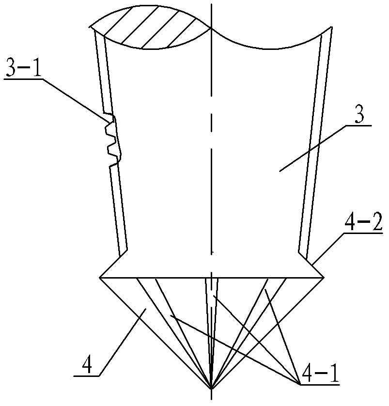
[0014] Specific implementation mode one: combine Figure 1 ~ Figure 3 Describe this embodiment. This embodiment includes a clamping body and a stirring body. The clamping body includes an upper cylinder 1 and a lower cylinder 2. The stirring body includes a main stirring needle 3 and an auxiliary stirring needle 4. The upper cylinder 1 and the lower cylinder The body 2, the main stirring needle 3, and the auxiliary stirring needle 4 are arranged in sequence from top to bottom and are made into one body. The diameter of the upper cylinder 1 is smaller than the diameter of the lower cylinder 2, and a clip is provided on the outer surface of the upper cylinder 1. The holding surface 1-1, the outer surface of the lower cylinder 2 is provided with at least two annular heat insulation grooves 2-1, the main stirring needle 3 is a cone, the diameter of the upper end of the main stirring needle 3 is greater than the diameter of the lower end, the main stirring needle 3 The outer surfac...

specific Embodiment approach 2

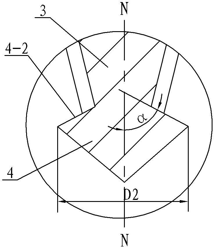
[0015] Specific implementation mode two: combination image 3 To describe this embodiment, the angle between the convex shoulder surface 4-2 and the central axis N-N of the welding tool in this embodiment is the lower angle α, and the lower angle α is 45°-75°. The convex shoulder surface 4-2 is the shoulder surface of the auxiliary stirring needle 4. Other components and connections are the same as those in the first embodiment.

specific Embodiment approach 3

[0016] Specific implementation mode three: combination figure 1 To illustrate this embodiment, the angle between the concave shoulder surface 2-2 and the central axis N-N of the welding tool in this embodiment is an upper angle β, and the upper angle β is 78°-82°. Other components and connections are the same as those in the first embodiment.


PUM


Abstract

The invention discloses a soldering set for agitating friction welding with an adjustable inclined angle and a concave-top and convex-bottom type shaft shoulder and a method thereof, relating to a soldering set for agitating friction welding and a method thereof. With the invention, the problems that a leading-in hole and a leading-out hole are required to be pre-fabricated in the conventional dual-shaft shoulder self-held agitating friction welding, and the thermal input amount in the agitating friction welding process is too large to cause decreased joint performance are solved. The soldering set comprises an upper cylinder, a lower cylinder, a main agitating needle, an auxiliary agitating needle which are orderly arranged from top to bottom and fabricated into one piece, the lower end face of the lower cylinder is a concave shaft shoulder face, and the upper end face of the auxiliary agitating needle is a convex shaft shoulder face. The method comprises the following steps of determining size of the auxiliary agitating needle; determining a lower included angle between the convex shaft shoulder face and the soldering set central axis; determining use length of an agitating body; determining an upper included angle between the concave shaft shoulder face and the soldering set central axis; adjusting the inclined angle of soldering set; and carrying out the agitating frictionwelding of a hollow unbraced structure. The invention is used for soldering the hollow unbraced structure.

Description

technical field [0001] The invention relates to a welding tool and method for friction stir welding, in particular to a welding tool used for hollow unsupported structures and whose inclination angle can be adjusted during friction stir welding. Background technique [0002] As an advanced solid-phase joining technology, friction stir welding has been invented by The Welding Institute (TWI) in 1991. Due to its small welding deformation, small residual stress, good joint quality and fine weld seam Crystal forged microstructure, no need for protective gas and filling materials, can eliminate welding defects such as pores, inclusions, cracks, etc., and does not produce arc light, smoke, noise pollution, etc., and has the characteristics of simple welding operation, convenient automatic welding, and high welding efficiency. Friction welding has been widely used in many industrial manufacturing fields such as aerospace, aviation, shipbuilding, trains, automobiles, and electric po...

Claims


Application Information

Patent Timeline
Patent Type & Authority Applications(China)
IPC IPC(8): B23K20/12B23K20/26
Inventor 黄永宪万龙吕世雄韩冰
Owner 安徽万宇机械设备科技有限公司
Why Eureka
Try Eureka