Deep hole machining cutter

A technology for processing cutting tools and deep holes, which is applied in the direction of manufacturing tools, metal processing equipment, and cutting tools for lathes, etc. It can solve the problems of affecting the accuracy of cutting tools, poor adjustment accuracy, and difficult retraction of combined boring heads.

Active Publication Date: 2012-07-18
德州普利森机床有限公司
View PDF8 Cites 10 Cited by
  • Summary
  • Abstract
  • Description
  • Claims
  • Application Information

AI Technical Summary

Problems solved by technology

[0005] The technical scheme recorded in CN101264575A solves the difficult problem of combined boring head retraction to a certain extent, but the technical means of installing the support half-ring when it is in the cutting state and removing the support half-ring when retracting the tool not only operates It is more troublesome, and frequent assembly operations will affect the accuracy of the tool
[0008] The structure disclosed in the above-mentioned CN102152118A is a relatively good attempt, and it is also applied in production practice, but because it performs the radial adjustment through a push rod with a relatively small aspect ratio and a nut, The load of the nut threaded with the ejector rod is too large but the thread length is relatively short, which is relatively easy to fail. Even if the thread does not fail, the adjustment accuracy will be poor due to thread deformation, which will affect the final machining accuracy.

Method used


Image

  • Deep hole machining cutter
  • Deep hole machining cutter
  • Deep hole machining cutter

Examples


Embodiment Construction

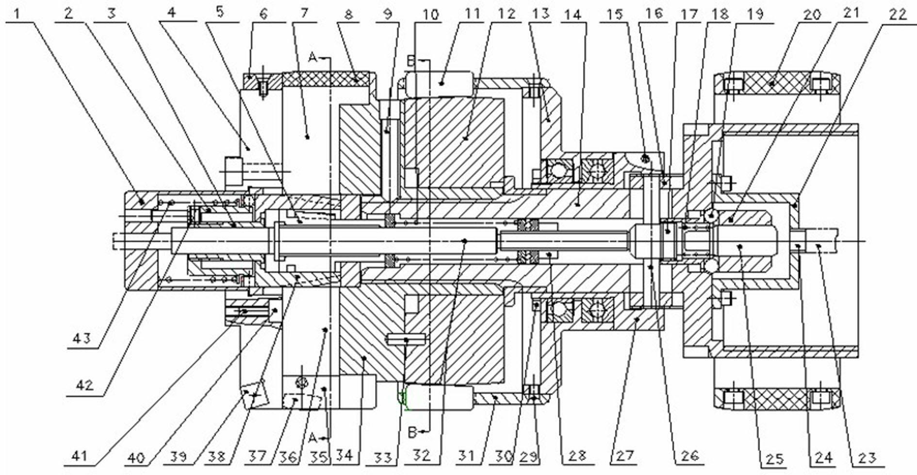
[0043] Refer to the attached figure 1It is a schematic diagram of the longitudinal section structure of a deep hole machining tool according to the present invention, which conforms to the preferred implementation mode adopted by the present invention, and those skilled in the art can select or modify related technical means according to the description of the preferred example. The names of the technical means used in the examples do not constitute specific limitations on their structures, and simple transformations of related technical means shall fall within the protection scope of the present invention.

[0044] A kind of deep hole machining tool is shown in the appendix of the manual figure 1 Among them, like the existing deep hole processing tool with expansion and contraction function, it has a tubular cutter body 14. Of course, the cutter body is not strictly a cylindrical tube, because there are many connection structures on the surface, mainly because the center cont...


PUM


Abstract

The invention discloses a deep hole machining cutter, which comprises a cutter body, a rough boring portion, a scraping portion and a rolling portion. The cutter body, the rough boring portion, the scraping portion and the rolling portion are assembled together to form a machining functional portion, a retainer of the rolling portion is an axial adjustable component of the cutter body, a roller is restrained in a raceway supporting portion with a second inclined surface by the retainer in the axial direction, an ejector rod positioned in the cutter body is arranged and connected with the retainer, the ejector rod and a top block match with each other in a threaded manner to form a top block moving threaded pair, the ejector rod is supported by a seat, a driving part for driving the ejector rod to rotate is disposed at the head end of the cutter, the degree of freedom of the seat moving along the axial direction of the cutter body is restrained, and the other end of the seat is restrained by a resetting device. The deep hole machining cutter can guarantee high machining precision under the condition that an expansion and contraction function of the cutter is realized.

Description

technical field [0001] The invention relates to a tool for deep hole processing, in particular to a combined deep hole tool with an automatic expansion and contraction mechanism for a deep hole boring-scraping-rolling compound tool, which includes an expansion and contraction structure for the surface forming part to facilitate deep hole processing Retraction during the process or after machining; deep hole refers to the inner hole with the ratio of the length of the hole to the diameter of the hole greater than 10. Background technique [0002] The Chinese No. CN102152118A patent application for invention is cited in its entirety. In order to facilitate understanding, retrieval and examination, the background technology part of the patent application for invention above is included in this application. [0003] It is well known that deep hole machining mostly uses a single-function tool. A simple compound tool is a boring and rolling compound tool, but this type of tool ca...

Claims


Application Information

Patent Timeline
Patent Type & Authority Applications(China)
IPC IPC(8): B23P23/00B23B27/00B23D79/04B23P9/02
Inventor 贾强战伯良鲁绪阁
Owner 德州普利森机床有限公司
Why Eureka
Try Eureka