Supercharge Your Innovation With Domain-Expert AI Agents!

Method for manufacturing side wall

A technology of tool manufacturing and molded parts, which is applied in applications, household components, household appliances, etc., can solve the problems of increasing manufacturing difficulty, and achieve the effect of optimizing the manufacturing process and good connection

Active Publication Date: 2012-07-18
MAGNA STEYR FAHRZEUGTECHN
View PDF7 Cites 2 Cited by
  • Summary
  • Abstract
  • Description
  • Claims
  • Application Information

AI Technical Summary

Problems solved by technology

[0004] This known method has disadvantages with respect to the production of the complete side wall: that is, after the side wall assembly has been completed, the side wall usually has to be further processed together with a large number of other components in other relatively complex method steps
Especially lightweight constructions with mixed materials significantly increase manufacturing difficulties due to, for example, galvanic corrosion and the many different joining methods to be used

Method used


Image

  • Method for manufacturing side wall
  • Method for manufacturing side wall
  • Method for manufacturing side wall

Examples


Embodiment Construction

[0021] First of all, it should be clear that in the various embodiments described, the same reference signs or the same component signs are used for the same components, wherein the disclosure content contained in the entire description can also be transferred to the same parts according to their meaning. On the same part with the same reference number or the same component number. Selected positions in the description, such as top, bottom, side, etc., also relate to the direct description and the illustrated figures, and in the event of a change in position, also change over to the new position according to their meaning. These figures are additionally described collectively.

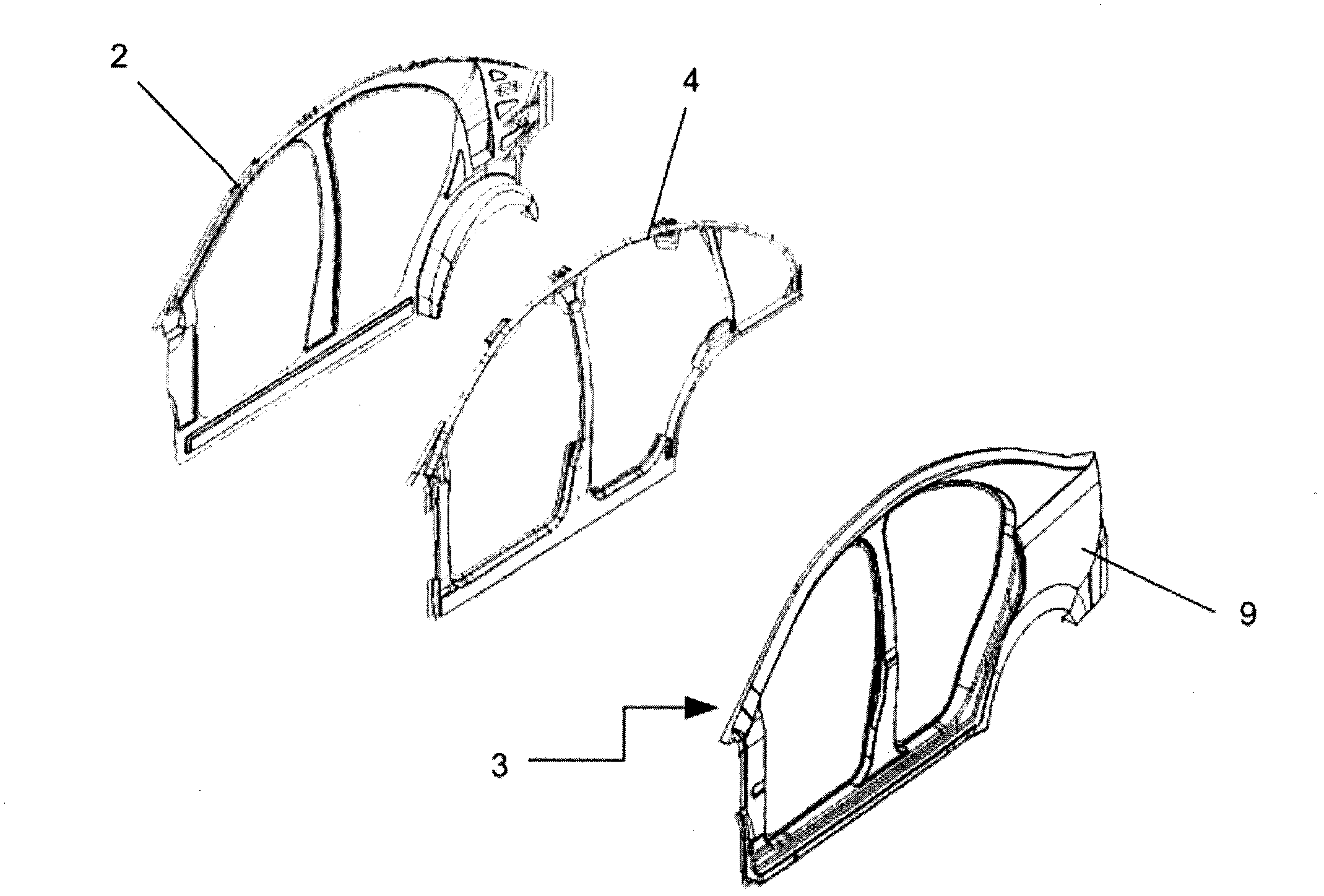
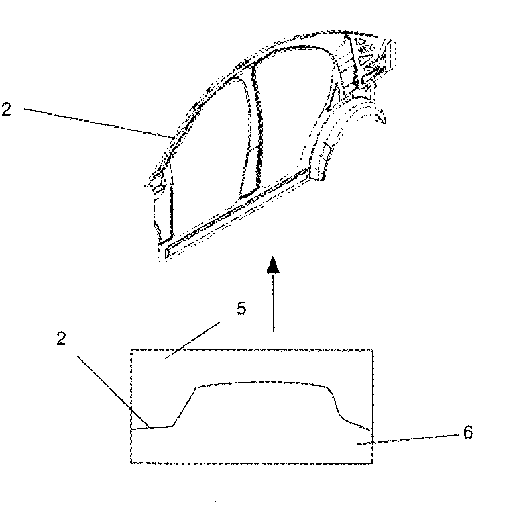
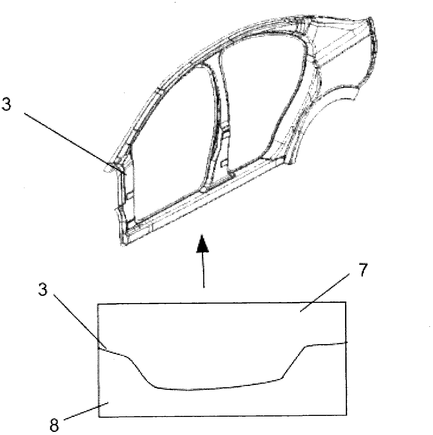
[0022] according to figure 1 , the side wall 1 according to the invention has two plastic shells 2 , 3 and a metal structure 4 located between the plastic shells 2 and 3 . The plastic shells 2 and 3 are preferably made of continuous fibre-reinforced thermoplastic. The metal structure 4 can be design...


PUM


Abstract

The method involves constructing a side wall having two plastic shells (2,3) made of thermoplastic and a reinforcing metal structure (4). The shaping of the plastic shells is carried out by four molding units (5). The coating (9), particularly polyurethane foam is introduced into a fifth molding unit (10). The fourth molding unit is removed and the latter plastic shell remains on the third molding unit. The metal structure is adhered with the latter plastic shell.

Description

technical field [0001] The invention relates to a method for producing side walls of motor vehicle bodies by using at least one stamping tool. [0002] In addition, the invention also relates to a side wall for a motor vehicle body. Background technique [0003] A related embossing method for producing components of side walls of motor vehicle bodies, in particular trim and lining parts of the side walls, is known, for example, from DE 10 2007 024 530 . In this known method, the material forming the decorative layer, the plastic-molding material forming the carrier and the extensible material for forming the extensible lining are introduced into the molding cavity of the molding tool opening and / or positioned in the in the molding cavity. The molding tool consists of at least two shaped parts, namely an upper part and a lower part. The shaped parts can be moved away from and towards each other. Formed between the upper part and the lower part is a molding cavity, which i...

Claims


Application Information

Patent Timeline
Patent Type & Authority Applications(China)
IPC IPC(8): B29C43/18B29C43/20B29C70/08B29C70/46B60R13/02B62D25/02
CPCB29C70/46B29C43/14B62D25/02B29C70/44B62D29/04B29C44/086B29L2031/3055B29C43/18B29C70/86
Inventor B·霍佛B·塞波克
Owner MAGNA STEYR FAHRZEUGTECHN
Features
  • R&D
  • Intellectual Property
  • Life Sciences
  • Materials
  • Tech Scout
  • Unparalleled Data Quality
  • Higher Quality Content
  • 60% Fewer Hallucinations
Learn More