Ink oscillating device for offset machine

A technology for offset printing machines and inking rollers, which is applied to printing machines, general parts of printing machinery, printing, etc., can solve the problem of short service life and complexity; the second is a composite type, and the outer shell of the inking roller The public sleeve has a spiral groove on it, and balls are installed in the groove, so as to separate from the fixed bush installed on the inner wall of the outer shell of the ink roller, and the ball is attached to the ring groove of the fixed bush, and the fixed bush passes through The ball bearing and the inking roller shaft are installed together. When the outer shell of the inking roller is driven by power to rotate in the circumferential direction, it will affect the transmission accuracy and life of the inking gear, so as to achieve long service life, simple structure and avoid sliding wear.

Inactive Publication Date: 2012-07-18
汕头市东源轻工机械厂有限公司
View PDF6 Cites 0 Cited by
  • Summary
  • Abstract
  • Description
  • Claims
  • Application Information

AI Technical Summary

Problems solved by technology

There are generally three schemes in the prior art: one is the crank rocker mechanism type, on one side (operating surface) of the wallboard of the offset printing machine, the power drive is the inking gear installed on the inking roller shaft, thereby driving the inking The roller rotates in the circumferential direction, and a crank and rocker mechanism is installed on the other side (transmission surface) of the wallboard of the offset printing machine. The connecting rod drives the string ink roller to move axially through the roller on the swing rod. Adjustable, but the disadvantage is that the structure is complex; the second is the compound type, the outer casing of the ink roller is equipped with a common sleeve, and there is a spiral groove on it, and the ball is installed in the groove, so as to be installed in the outer shell of the ink roller. The fixed bushing on the inner wall of the body is separated, and the balls are attached to the ring groove of the fixed bushing. The fixed bushing is assembled with the shaft of the inking roller through the ball bearing. When the outer shell of the inking roller is driven by power When rotating, the common sleeve does not rotate, and the spiral groove on it forces the outer shell of the ink roller to move axially through the balls. The advantage is that the

Method used


Image

  • Ink oscillating device for offset machine
  • Ink oscillating device for offset machine
  • Ink oscillating device for offset machine

Examples


Embodiment Construction

[0012] Further description will be given below in conjunction with the accompanying drawings and preferred embodiments of the present invention.

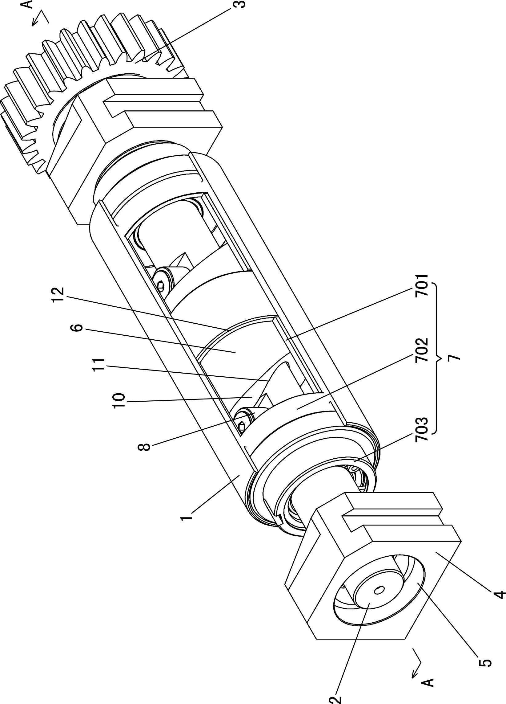
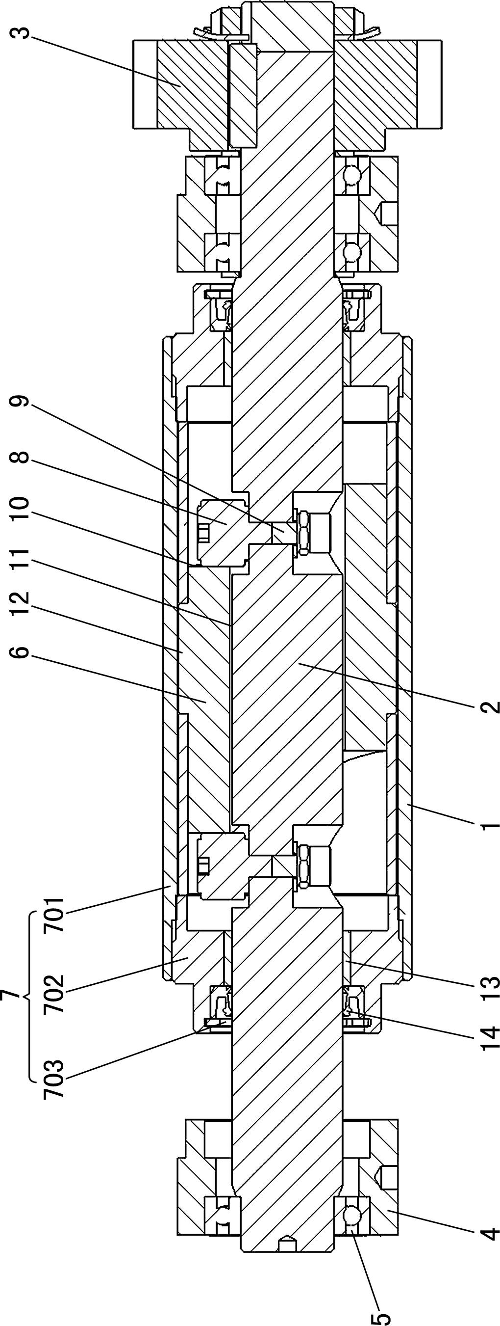
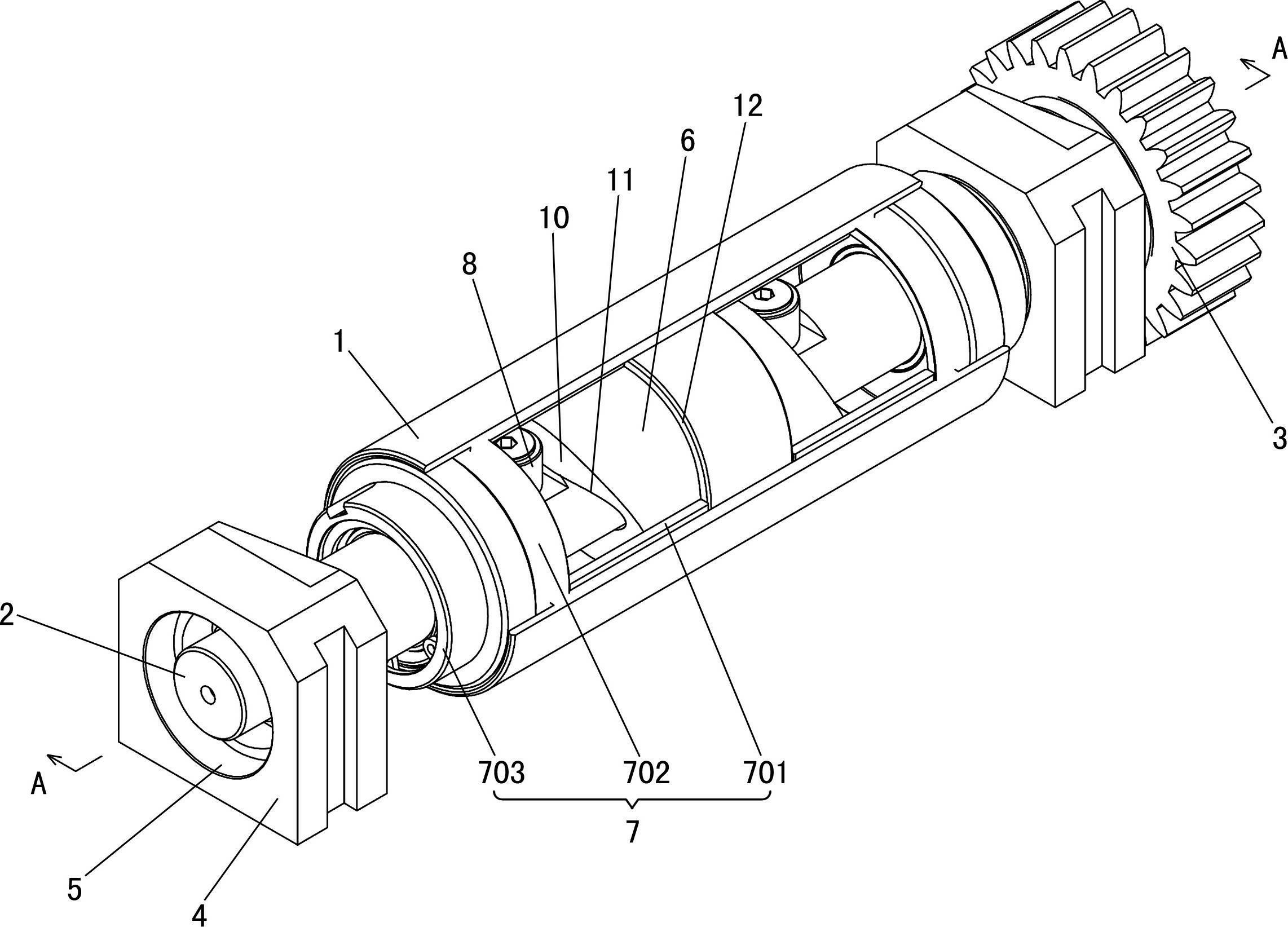
[0013] Such as figure 1 and figure 2 As shown, the inking device of this offset printing machine includes an inking roller 1, an inking roller shaft 2, an inking gear 3, two bearing seats 4, two bearings 5, an end cylindrical cam 6, a fastening mechanism 7, two A cam roller 8 and two roller connecting shafts 9; the string ink roller shaft 2 is in the inner chamber of the string ink roller 1, and the two ends of the string ink roller shaft 2 are respectively installed on the bearing housing 4 through the bearing 5; the string ink roller The gear 3 is in transmission connection with one end of the ink roller rotating shaft 2; the end face cylindrical cam 6 has two end faces 10, and along the axial direction of the end face cylindrical cam 6, the distances between two corresponding points on the two end faces 10 are equal; the end fa...


PUM


Abstract

The invention relates to an ink oscillating device for an offset machine, comprising an ink oscillating rod, an ink oscillating rod rotating shaft, an ink oscillating gear, two bearing pedestals and two bearings. The ink oscillating device for the offset machine is characterized by further comprising an end-face cylindrical cam, a fastening mechanism, two cam rollers and two roller connecting shafts. The end-face cylindrical cam is provided with a round sliding through hole in the axis direction; the ink oscillating rod rotating shaft is arranged in the round sliding through hole; the cylindrical surface of the end-face cylindrical cam is connected with the inner side wall of the ink oscillating rod through a fastening mechanism; the two cam rollers are arranged on the ink oscillating rod rotating shaft through the two roller connecting shafts and are located at the two ends of the end-face cylindrical cam; and the two cam rollers are in contact match with the corresponding end surfaces. The ink oscillating device for the offset machine has a simpler and compacter structure; the ink oscillating gear cannot slide on the shaft to wear, so that the transmission precision and the service life of the ink oscillating gear cannot be affected, and the ink oscillating gear has longer service life; and the ink oscillating amount of the ink oscillating rod can be adjusted conveniently by adjusting the installation position of the cam rollers on the roller connecting shafts.

Description

technical field [0001] The invention relates to a printing device, in particular to an ink string device of an offset printing machine. Background technique [0002] The role of the inking device of the offset printing machine is to twist and thin the ink layer through the mutual rolling between the ink roller and the ink distribution roller, and the simultaneous axial movement of the ink roller. There are generally three schemes in the prior art: one is the crank rocker mechanism type, on one side (operating surface) of the wallboard of the offset printing machine, the power drive is the inking gear installed on the inking roller shaft, thereby driving the inking The roller rotates in the circumferential direction, and a crank and rocker mechanism is installed on the other side (transmission surface) of the wallboard of the offset printing machine. The connecting rod drives the string ink roller to move axially through the roller on the swing rod. Adjustable, but the disad...

Claims


Application Information

Patent Timeline
IPC IPC(8): B41F31/14
Inventor 黄梓成
Owner 汕头市东源轻工机械厂有限公司
Why Eureka
Try Eureka