Connection system for total-prefabricated concrete structure

A prefabricated concrete and connection system technology, applied to building components, building structures, walls, etc., can solve the problems of increased concrete construction wet work, poor seismic performance, poor reliability, etc., to achieve easy construction quality assurance, convenient construction, The effect of building speed

Inactive Publication Date: 2012-07-18
TONGJI UNIV
View PDF7 Cites 3 Cited by
  • Summary
  • Abstract
  • Description
  • Claims
  • Application Information

AI Technical Summary

Problems solved by technology

The disadvantage of this connection method is irregularity, poor reliability, and poor seismic performance. After welding, concrete is required to fill the gap in the overhanging part of the steel bar, which increases the wet work load of concrete construction.

Method used


Image

  • Connection system for total-prefabricated concrete structure
  • Connection system for total-prefabricated concrete structure
  • Connection system for total-prefabricated concrete structure

Examples


Embodiment 1

[0052] In a preferred embodiment of the invention, the structure is used for beam-to-column connections.

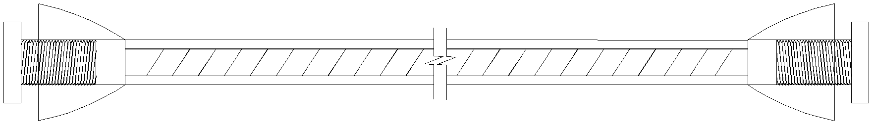
[0053] Such as Figure 10 , Figure 11 , Figure 12 , Figure 13 , Figure 14 , Figure 15 Shown: the prefabricated component 10 is produced and processed in the prefabrication factory with threaded steel bar 7 / 8 / 9 at the end. When pouring concrete, the threaded part at the end of the threaded steel bar 7 / 8 must be exposed, or ensure that the threaded steel bar at the end 9. The section of the end is kept flush with the prefabricated component 10, and the end sleeve of the threaded steel bar 9 is poured into the prefabricated component 10. The position of the threaded steel bar 7 / 8 / 9 at the end is respectively connected with the column belt straight stiffener single web connector ( Figure 4 ), single web connectors with oblique stiffeners ( Figure 5 ), wall double web connectors ( Image 6 ) corresponding to the positions of the screw holes 12, and the threaded ...

Embodiment 2

[0055] In a preferred embodiment of the invention, the structure is used for wall connection.

[0056] Such as Figure 16 , Figure 17 , Figure 18 , Figure 19 , Figure 20 , Figure 21 , Figure 22 , Figure 23 , Figure 24 , Figure 25 As shown, the embodiment of the wall connection of the present invention is: the prefabricated component 10 adopts the threaded steel bar 7 / 8 / 9 at the end to be produced and processed in the prefabrication plant. When pouring concrete, the threaded part at the end of the threaded steel bar 7 / 8 must be Expose, or ensure that the cross section of the end of the upsetting internally threaded steel bar 9 is kept flush with the prefabricated component 10 , and pour the sleeve of the end of the upset internally threaded steel bar 9 into the prefabricated component 10 . The positions of the threaded steel bars 7 / 8 / 9 at the end are respectively connected to the wall single web connectors ( Figure 7 ), single web connector with stiffened si...


PUM


Abstract

The invention belongs to the field of design and construction of a prefabricated concrete structure, in particular to a total-prefabricated concrete structure and a component connection constitution. The connection system includes reinforcing steel bars, a connection member and a fastening device, and the reinforcing steel bars are connected with the connection member via the fastening device. The system has the following advantages that the construction speed is quick, the connection performance is reliable, the construction method is advanced, the construction quality is easily guaranteed and the prefabricated components can be reusable. The connection member can not only be rationally connected with reinforcing steel bars in the prefabricated components, but also achieve connection between prefabricated components. On-site work in the invention is basically dry work, various defects of cast-in-situation concrete are fully avoided, the construction cost is reduced, the construction funds are saved, and the ecological environment is protected. The invention has advantages of reliable theoretic basis, rational structure and convenient construction; and the required components are suitable for mass production in the factory for prefabrication.

Description

technical field [0001] The invention belongs to the field of prefabricated concrete structure design and construction, and relates to a connection system of a fully assembled prefabricated concrete structure. Background technique [0002] One of the key points of the fully assembled precast concrete structure is the connection structure between the structural members. In the prior art, the connection of prefabricated components is mainly through bolts or anchors, which makes it difficult to handle the steel bars in the prefabricated components. In the design and construction of the post-cast monolithic concrete structure, the connection between two prefabricated components is mainly by steel bar lapping, welding or connection and fixation of special connectors, and the method of post-casting concrete on site. The disadvantage of this connection method is irregularity, poor reliability, and poor seismic performance. After welding, concrete is required to fill the gap in the ...

Claims


Application Information

Patent Timeline
Patent Type & Authority Applications(China)
IPC IPC(8): E04B1/04E04B1/41E04B2/64
Inventor 吕西林赵斌贺娟
Owner TONGJI UNIV
Why Eureka
Try Eureka