Swinging buckling restrained brace and frame structure system and construction method thereof

A technology of anti-buckling support and frame structure, applied in the direction of earthquake resistance, building components, building structures, etc., can solve the problems of difficult guarantee of safety, strong compressive capacity, weak tensile capacity, etc., and achieve good energy consumption and shock absorption effect, The effect of high structural rigidity and easy replacement

Inactive Publication Date: 2012-07-18
BEIJING UNIVERSITY OF CIVIL ENGINEERING AND ARCHITECTURE
View PDF9 Cites 14 Cited by
  • Summary
  • Abstract
  • Description
  • Claims
  • Application Information

AI Technical Summary

Problems solved by technology

The foundation has strong compressive capacity and weak tensile capacity, making it difficult to guarantee safety
In the case of significant tensile, bending and shearing forces, foundation design is e

Method used


Image

  • Swinging buckling restrained brace and frame structure system and construction method thereof
  • Swinging buckling restrained brace and frame structure system and construction method thereof
  • Swinging buckling restrained brace and frame structure system and construction method thereof

Examples


Embodiment 1

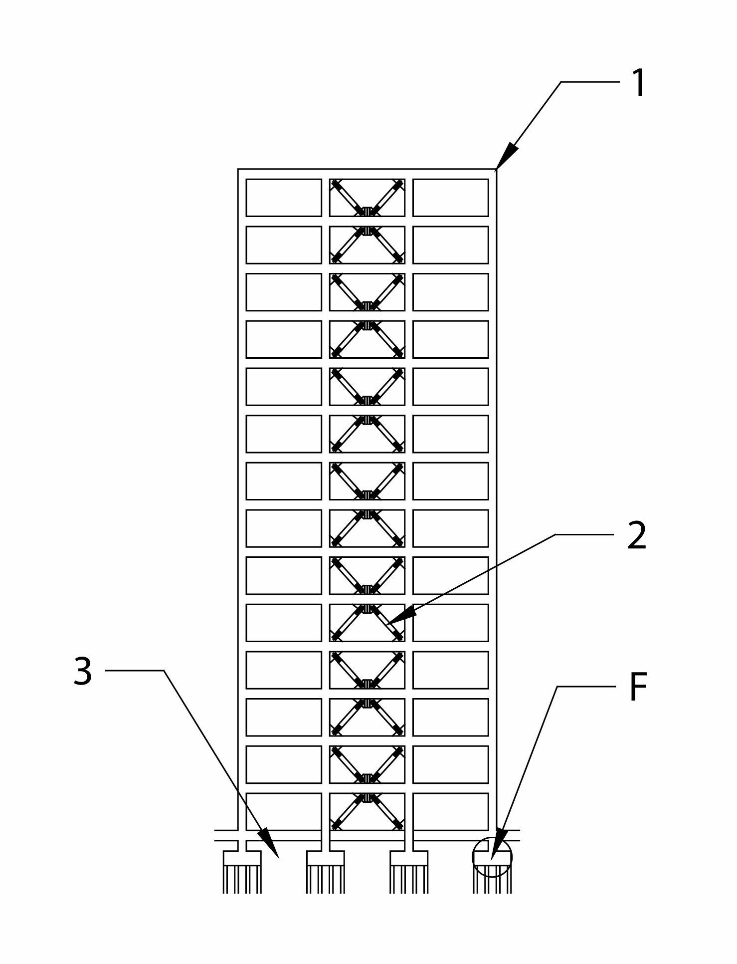
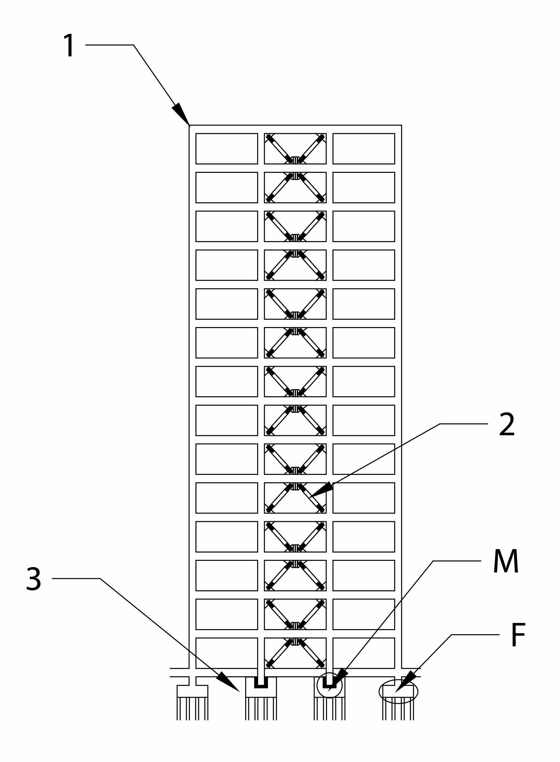
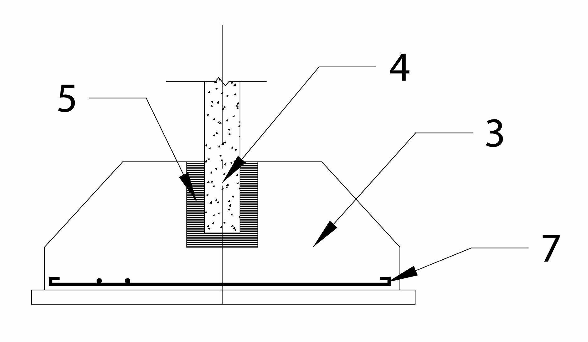
[0037] Example 1: The present invention is used in a reinforced concrete structure. The frame 1 is a reinforced concrete frame. The anti-buckling support 2 is installed between the frame column 4 and the frame beam 6 in the middle span of the rigid concrete frame. 2 The special structure avoids the problem of buckling of the reinforced concrete frame in the center. It can yield without buckling under tension and compression, which can better consume the seismic energy input to the structure. The connection between the bottom end of the frame column 4 of the reinforced concrete frame without the anti-buckling support 2 and the foundation 3 adopts the fixed end F, and the connection between the bottom end of the frame column 4 of the reinforced concrete frame with the anti-buckling support 2 and the foundation 3 adopts Embedded end M. Pre-embedded parts are provided on the bottom and surrounding surfaces of the frame column 4 of the reinforced concrete frame with the anti-bucklin...

Embodiment 2

[0038] Embodiment 2: The present invention is used in a steel structure. The frame 1 is a steel frame. An anti-buckling support 2 is installed in the middle of the steel frame. The special structure of the anti-buckling support 2 prevents the central steel frame from buckling under compression. The problem is that it can yield without buckling under tension and compression, which can better consume the seismic energy input to the structure. The bottom end of the frame column 4 of the rigid frame without the anti-buckling support 2 is connected to the foundation 3 by a fixed end F, and the bottom end of the frame column 4 of the rigid frame with the anti-buckling support 4 is connected with the foundation 3 by embedded fixing End M. Embedded parts are provided on the foundation 3 contacting the bottom end of the frame column 4 of the rigid frame on which the anti-buckling support 2 is installed. The rigid frame with the anti-buckling support 2 is connected to the embedded parts...


PUM


Abstract

Disclosed are a swinging buckling restrained brace and frame structure system and a construction method thereof. The swinging buckling restrained brace and frame structure system comprises a buckling restrained brace, a frame, a foundation, fixing ends and embedded ends, the buckling restrained brace is mounted on the frame, and the frame is fixed onto the foundation by the aid of the fixing ends and the embedded ends. The swinging buckling restrained brace and frame structure system and the construction method are mainly characterized in that restraint on the fixing ends of columns of the frame with the brace and restraint on the foundation are released, and the embedded ends of an energy consuming element are vertically disposed. The system is high in structural rigidity, and seldom moves when in earthquake, energy consuming and damping effects are good, and the buckling restrained brace which is used as a replaceable energy dissipation unit can be conveniently replaced after earthquake.

Description

Technical field [0001] The invention relates to the technical field of civil engineering structures, in particular to a swing anti-buckling support-frame structure system and a construction method thereof. Background technique [0002] The traditional seismic design method allows the structure to enter a non-linear state during a strong earthquake, relying on the elastoplastic deformation of the main structure and components to dissipate the input energy of ground motions, and realize the building structure "small earthquakes are not bad, moderate earthquakes can be repaired, and large earthquakes. "Don't fall" as the anti-seismic fortification target. However, the structure and components are subjected to complex reciprocating loads during the earthquake, which makes it difficult to determine the degree of cumulative damage quantitatively, which makes it difficult to repair most damaged structures after the earthquake, and has to be demolished and reconstructed, resulting in a h...

Claims


Application Information

Patent Timeline
IPC IPC(8): E04B1/98E04G21/14
Inventor 吴徽徐斌张国伟彭有开张艳霞张扬
Owner BEIJING UNIVERSITY OF CIVIL ENGINEERING AND ARCHITECTURE
Why Eureka
Try Eureka