Method and device for detecting gas content of mixed fluid under while drilling condition

A technology of mixing fluids and detection devices, which can be used in measurement, earthmoving, wellbore/well components, etc., and can solve the problems of inaccurate measurement results and lag in detection results.

Active Publication Date: 2012-07-18
BC P INC CHINA NAT PETROLEUM CORP +1
View PDF4 Cites 18 Cited by
  • Summary
  • Abstract
  • Description
  • Claims
  • Application Information

AI Technical Summary

Problems solved by technology

[0009] In order to overcome the problems of hysteresis and inaccurate measurement results of mixed fluid gas content detection in the prior art, the present invention provides a method and device for detection of mixed fluid gas content under drilling conditions

Method used


Image

  • Method and device for detecting gas content of mixed fluid under while drilling condition
  • Method and device for detecting gas content of mixed fluid under while drilling condition
  • Method and device for detecting gas content of mixed fluid under while drilling condition

Examples


Embodiment 1

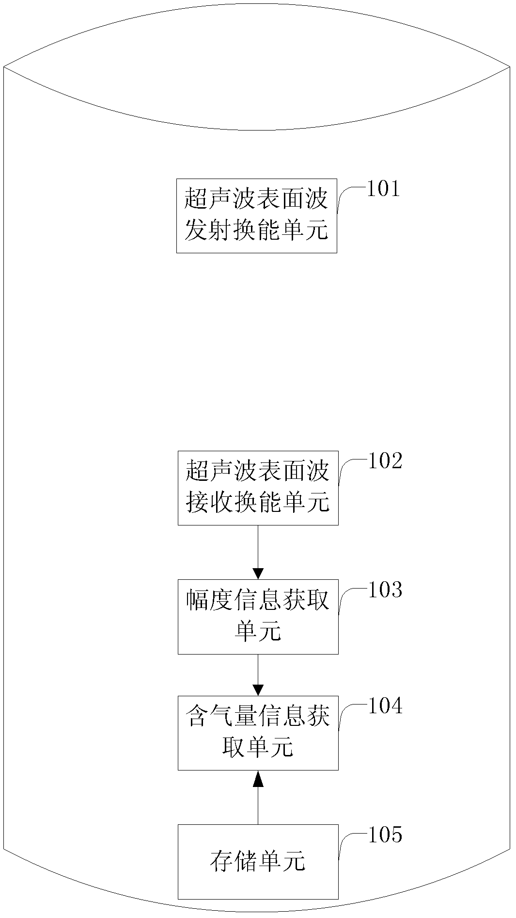
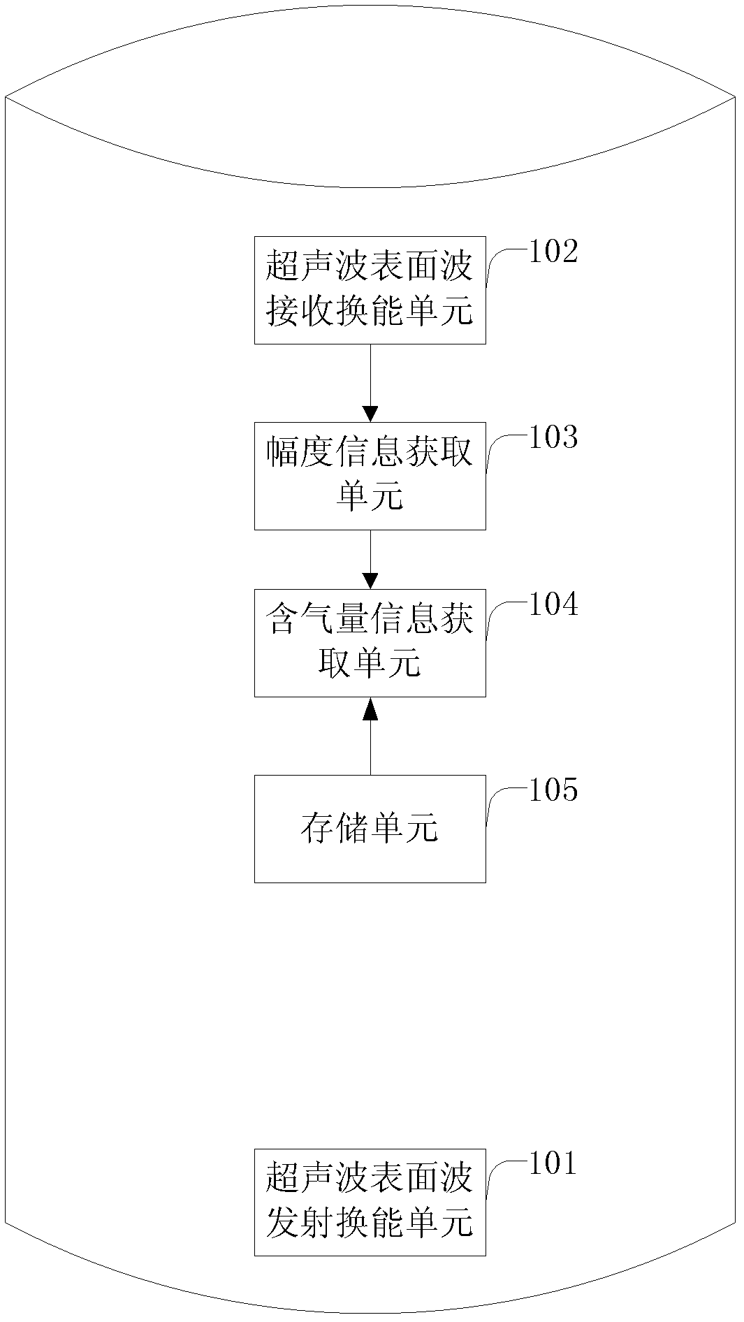
[0029] figure 1 It is a structural diagram of a mixed fluid gas content detection device under the condition of drilling provided by the embodiment of the present invention, as shown in figure 1 As shown, the gas content detection device includes: a surface ultrasonic wave transmitting and transducing unit 101 , a surface ultrasonic wave receiving transducing unit 102 , an amplitude information obtaining unit 103 , a gas content information obtaining unit 104 and a storage unit 105 . Focusing on the practicability of the probe, easy disassembly and interchange, and independent testing and verification of the probe function, the ultrasonic surface wave sensors involved in the embodiments of the present invention all adopt a modular structure, and these probe modules are composed of piezoelectric vibrators and necessary The packaging components can respectively have the functions of transmitting ultrasonic surface wave signals and receiving ultrasonic surface wave signals, and c...

Embodiment 2

[0043] Figure 4 It is a flow chart of a method for detecting the gas content of mixed fluid under drilling conditions provided by the embodiment of the present invention, as shown in Figure 4 As shown, the gas content detection method comprises the following steps:

[0044] S401. Generating ultrasonic surface waves through electric signal excitation.

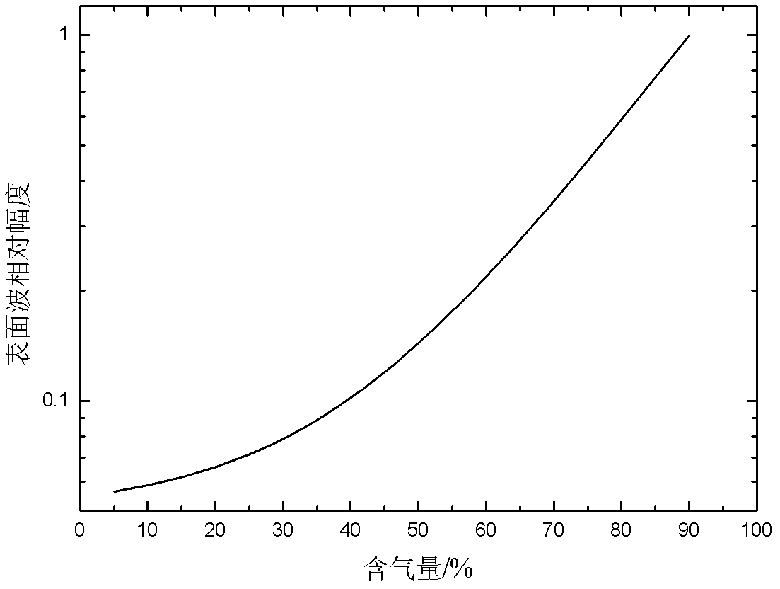
[0045] In the embodiment of the present invention, the gas content detection method can be realized by the gas content detection device in Embodiment 1. The gas content detection device can have an ultrasonic surface wave transducer, and its operating frequency range is about 0.5 MHz to 3 MHz. Here The wavelength of the ultrasonic surface wave in the working frequency range is much smaller than the wall thickness of the drill collar, so the drill collar can be regarded as a semi-infinite solid medium, and the fluid outside the outer surface of the drill collar can be regarded as a mixture of liquid and gas composite fluid me...


PUM


Abstract

The invention relates to a method and a device for detecting gas content of a mixed fluid under a while drilling condition. The method comprises the steps of: exciting through an electric signal to generate an ultrasonic surface wave; receiving the ultrasonic surface wave; obtaining amplitude information of the received ultrasonic surface wave; and obtaining the gas content information of the mixed fluid according to the amplitude information. According to the invention, the gas content of fluids in wells can be correctly and quantitatively measured in real time, the underground geological conditions can be known, the information of oil and gas layers can be discovered in time and the wastes of oil and gas resources can be avoided; and the method and the device can be used for recognizing overpressure stratums and treatment can be carried out in time when overpressure stratums are drilled, so that the occurrences of well kick and well blowout are prevented, the heavy losses of personal lives and properties are avoided, and reference information can be provided for the drilling track regulation in the drilling process.

Description

technical field [0001] The invention relates to the technical field of petroleum exploration and development, in particular to the technical field of gas content detection of mixed fluids, in particular to a method and device for detecting gas content of mixed fluids under drilling conditions. Background technique [0002] Oil drilling is the most direct way to discover oil and gas reservoirs, and safe and efficient drilling is the most prominent issue in petroleum engineering. The sudden entry of gas in the formation into the wellbore is one of the main reasons for various safety accidents during the drilling process. How to detect the gas in the drilling fluid in time is one of the most important drilling safety measures. [0003] During the drilling process, when the drill bit encounters an oil-bearing or gas-bearing formation, the gas in the formation may enter the well and mix into the drilling fluid to form a mixed phase medium of gas and liquid. It is very important t...

Claims


Application Information

Patent Timeline
Patent Type & Authority Applications(China)
IPC IPC(8): E21B47/14E21B49/08
Inventor 车小花乔文孝鞠晓东卢俊强
Owner BC P INC CHINA NAT PETROLEUM CORP
Why Eureka
Try Eureka