Multiple-interlayer salt cavern gas storage and building method of multiple-interlayer salt cavern gas storage

A construction method and technology for gas storage, which are applied in earth-moving drilling, mining equipment, mining equipment, etc., can solve the problems of low strength, small thickness, collapse, etc., and achieve strong operability, good generalizability, and increased cost. Effect

Inactive Publication Date: 2012-07-18
CHINA UNIV OF PETROLEUM (EAST CHINA)
View PDF8 Cites 25 Cited by
  • Summary
  • Abstract
  • Description
  • Claims
  • Application Information

AI Technical Summary

Problems solved by technology

In order to ensure the volume of the salt cavern gas storage, it is necessary to increase the diameter of the salt cavern, so that the top salt layer and interlayer bear more self-weight, resulting in the stability of the top of the salt cavern in the multi-interlayer formation and the gas storage in the salt dome type formation. Significantly lower than
At the same time, due to the small thickness and low strength of each layer of multi-layered salt rock, the possibility of instability of the gas storage is exacerbated.
In the existing technology, in the design process of the top of the salt cavern gas storage, the top of the salt cavern gas storage is often designed as a pressure arch structure with good stability. In fact, the interlay

Method used


Image

  • Multiple-interlayer salt cavern gas storage and building method of multiple-interlayer salt cavern gas storage
  • Multiple-interlayer salt cavern gas storage and building method of multiple-interlayer salt cavern gas storage

Examples


Example Embodiment

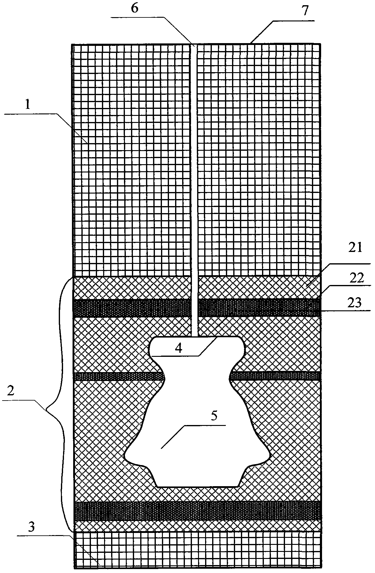
[0020] Such as figure 1 As shown, the multi-interlayer salt cavern gas storage includes a salt cavern 5 and a natural gas injection and production string system 6; the natural gas injection and production string system 6 is connected to the top of the salt cavern 5; from the ground 7 downwards are the top mudstone 1, multiple interlayers Salt rock 2, bottom mudstone 3; multi-interlayer salt rock is composed of salt layers and interlayers, and the salt layers and interlayers appear alternately; the salt cavern is located in the multi-interlayer salt rock, and the top surface 4 of the salt cavern is circular. From the bottom surface of the mudstone at the top to the top surface of the salt cavern are the first salt salt layer 21, the interlayer 22 and the second salt salt layer 23 in sequence. The top buried depth of the salt cavern is 951.2m, the bottom buried depth is 1045m, the minimum operating pressure is 6MPa and the minimum pressure operating time is 45 days. The design v...


PUM

PropertyMeasurementUnit
Thicknessaaaaaaaaaa
Thicknessaaaaaaaaaa
Thicknessaaaaaaaaaa

Abstract

The invention belongs to the field of oil and gas resource development and particularly relates to a multiple-interlayer salt cavern gas storage and a building method of the multiple-interlayer salt cavern gas storage. The multiple-interlayer salt cavern gas storage comprises a salt cavern and a natural gas injection-production string system, wherein the natural gas injection-production string system is connected with the top of the salt cavern. Top mud rocks, multiple-interlayer salt rocks and bottom mud rocks are sequentially arranged downwards from the ground. The multiple-interlayer salt rocks are composed of salt rocks and interlayers which alternately appear. The multiple-interlayer salt cavern gas storage is characterized in that the salt cavern is positioned in the multiple-interlayer salt rocks; a first salt rock layer, the interlayer and a second salt rock layer are sequentially arranged from the bottom of the top mud rocks to the top of the salt cavern; and the top of the salt cavern is in the shape of circular plane. The building method of the multiple-interlayer salt cavern gas storage comprises the following steps of: selecting top structure, drilling a well, completing the well, installing the injection-production string, carrying out solution mining, and controlling the size of the top structure. According to the building method, the characteristics of the top structure of the multiple-interlayer salt cavern gas storage are mainly considered, the parameters of the size of the top structure are provided, the operability is strong, and the cost is not obviously increased. The building method is good in popularization.

Description

technical field [0001] The invention belongs to the field of oil and gas resource development, and in particular relates to a multi-interlayer salt cavern gas storage and a construction method thereof. Background technique [0002] The height of the salt-cavern gas storage in the multi-interlayered salt rock formation mainly depends on the thickness of the salt rock, which is much smaller than the height of the gas storage in the salt dome type. In order to ensure the volume of the salt cavern gas storage, it is necessary to increase the diameter of the salt cavern, so that the top salt layer and interlayer bear more self-weight, resulting in the stability of the top of the salt cavern in the multi-interlayer formation and the gas storage in the salt dome type formation. Significantly lower than that. At the same time, due to the small thickness and low strength of each layer of multi-interlayer salt rock, the possibility of instability of the gas storage is exacerbated. I...

Claims


Application Information

Patent Timeline
IPC IPC(8): E21F17/16
Inventor 王同涛闫相祯杨秀娟
Owner CHINA UNIV OF PETROLEUM (EAST CHINA)
Why Eureka
Try Eureka