Roller cam follower

A technology of roller cams and moving parts, which is applied in the direction of engine components, machines/engines, mechanical equipment, etc., can solve problems such as cost, and achieve the effects of reducing grinding work, fast passing time, and economical manufacturing

Inactive Publication Date: 2012-07-18
SCHAEFFLER TECH AG & CO KG
View PDF9 Cites 13 Cited by
  • Summary
  • Abstract
  • Description
  • Claims
  • Application Information

AI Technical Summary

Problems solved by technology

Since the housing extends almost over the entire axial extent of the roller cam follower, its outer peripheral surface must be finely ground completely, which is expensive

Method used


Image

  • Roller cam follower
  • Roller cam follower
  • Roller cam follower

Examples


Embodiment Construction

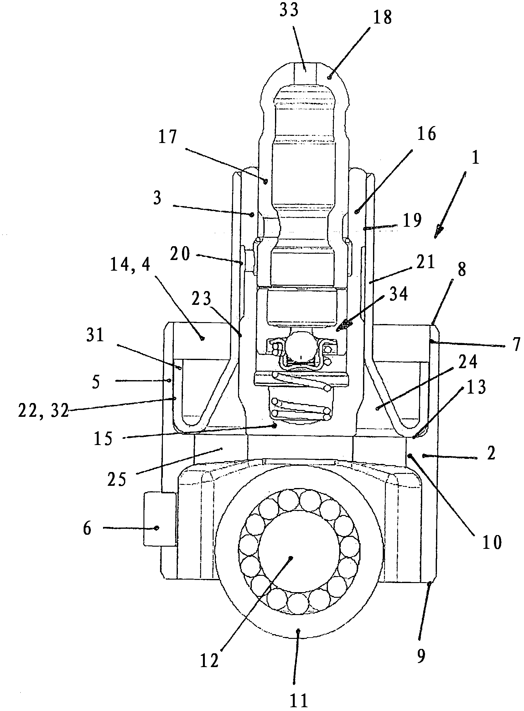
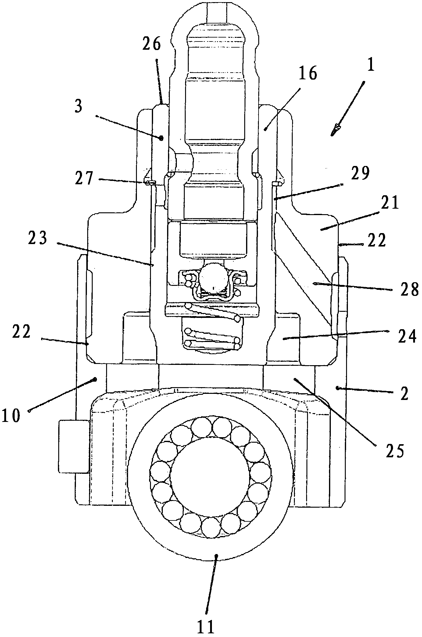
[0017] The figure shows the roller cam follower 1. The roller cam follower is used to reciprocate the rocker arm in the overhead valve mechanism with the camshaft located below. The roller cam follower is composed of a roller tappet 2 for reciprocating a piston of a high-pressure fuel pump and a hydraulic supporting element 3. The support element 3 here sits in the recess 4 of the roller tappet 2 formed by the upper side 13 of the bridge section 10 and the inner peripheral surface 7 of the housing 5. The adapter ring 21 serves as a connecting element.

[0018] The roller tappet 2 has a cylindrical casing 5 with a protruding anti-rotation fixing structure 6 which is here as a pin. The inner peripheral surface 7 of the casing is spaced apart from the edges 8, 9 of the casing 5, and is spanned by a bridging section 10 at approximately half the height (durchragen), and a cam roller 11 is provided below the bridging section, so The cam roller is supported on a pin 12 installed in t...


PUM


Abstract

The roller cam follower (1) comprises a hydraulic support unit (3) and a down or lateral cam shaft of an internal combustion engine. The roller cam follower is assembled from a roller shaft (2) for the stroke operation of a piston of a fuel high pressure pump and the hydraulic support unit. An independent claim is also included for a roller shaft has a support unit which is received in sections in a recess.

Description

Technical field [0001] The invention relates to a roller cam follower for reciprocating a rocker arm in an overhead valve mechanism of an internal combustion engine. The overhead valve mechanism has a camshaft located below or laterally above. Background technique [0002] This roller cam follower is made by DE 36 38 202 figure 1 Shown in. This roller cam follower has a relatively large mass, which disadvantageously becomes a vibrating valve train mass. The cam roller is accommodated in the recess of the housing and thus determines its radial extension over almost the entire height of the housing. Since the housing is nearly extended over the entire axial extension of the roller cam follower, its outer peripheral surface must be completely finely ground, which is costly. In addition, it has been confirmed that the construction / manufacturing of the roller cam follower, especially in small batches, is very costly, and it is usually necessary to redesign the roller cam follower fo...

Claims


Application Information

Patent Timeline
Patent Type & Authority Applications(China)
IPC IPC(8): F01L1/14F01L1/18
CPCF01L2105/00F01L2107/00F01L1/14F01L1/18F01L1/143F01L1/255F01L1/182F01L2305/00F01L2307/00
Inventor M·舍韦P·赛勒N·盖尔
Owner SCHAEFFLER TECH AG & CO KG
Why Eureka
Try Eureka