
Diesel engine for automobile and control method thereof

A diesel engine and engine technology, applied in the direction of engine control, engine components, combustion engines, etc., can solve problems such as difficult to meet self-ignition conditions, difficult to establish self-ignition conditions, and low temperature at the compression end

Inactive Publication Date: 2015-09-09
MAZDA MOTOR CORP
View PDF4 Cites 0 Cited by
  • Summary
  • Abstract
  • Description
  • Claims
  • Application Information

AI Technical Summary

Problems solved by technology

[0003] However, when the geometric compression ratio of a diesel engine is set low, the temperature at the compression end decreases accordingly, so it becomes difficult to satisfy the self-ignition conditions especially in the low-load and low-revolution operating range of the engine.
Furthermore, as shown in Patent Document 1, in a diesel engine, since the ignitability is affected by the properties of the supplied fuel (in particular, the lower the cetane number, the lower the ignitability), therefore, when compared with the operating conditions When factors related to the properties of the fuel are combined, the self-ignition condition becomes more difficult to establish

Method used


Image

  • Diesel engine for automobile and control method thereof
  • Diesel engine for automobile and control method thereof
  • Diesel engine for automobile and control method thereof

Examples


Embodiment approach 1

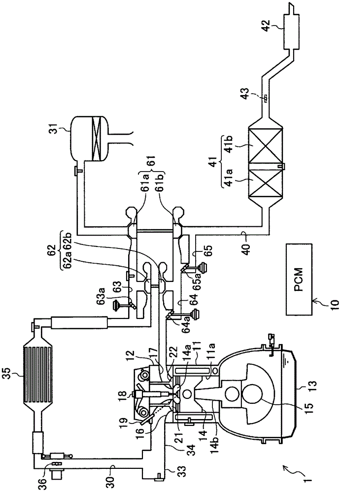
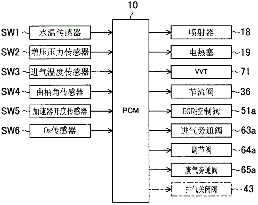
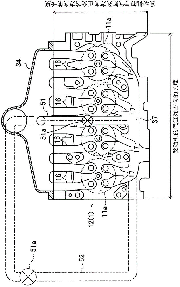
[0062] Hereinafter, a diesel engine according to Embodiment 1 of the present invention will be described based on the drawings. In addition, the description of the following specific embodiment is merely an illustration in nature. figure 1 , 2 The schematic configuration of the engine 1 according to the embodiment is shown. The engine 1 (engine main body) is a diesel engine mounted on a vehicle and supplied with a fuel mainly composed of light oil, and has a plurality of cylinders 11a ( figure 1 Only one cylinder block 11 is shown in (1), a cylinder head 12 provided on the cylinder block 11, and an oil pan 13 provided on the lower side of the cylinder block 11 and storing lubricating oil. Engine 1 in this example as image 3 As shown, it is an inline four-cylinder engine in which the first to fourth cylinders 11a are arranged in a row, but it is not limited to such an inline four-cylinder engine. Pistons 14 are inserted into each cylinder 11a of the engine 1 so as to recipro...

Embodiment approach 2

[0107]In Embodiment 1, the required EGR rate is achieved by introducing the burned gas into the cylinder 11a through the EGR passages 51 and 53 to ensure its ignitability. EGR rate to ensure ignition. Various methods can be employed in realizing the internal EGR, but here the internal EGR is realized by early closing of the exhaust valve 22 . That is, a negative overlap period in which both the intake valve 21 and the exhaust valve 22 are closed is provided in the exhaust stroke and the intake stroke, so that the burned gas remains in the cylinder 11a.

[0108] In this Embodiment 2, between the exhaust purification device 41 and the muffler 42 on the exhaust passage 40, a figure 1 and figure 2 The exhaust closing valve 43 (exhaust throttle valve) phantomly shown in FIG. The opening of the exhaust shutoff valve 43 is controlled by the PCM 10, and it is usually opened. However, as will be described later, in this example, the exhaust shutoff valve 43 may sometimes be under a...


PUM


Abstract

The disclosure provides a diesel engine, which includes an engine body mounted in a vehicle and having a cylinder to be supplied with fuel containing diesel fuel as its main component, a geometric compression ratio ε of the cylinder being set within a range of 12:1 to 15:1, and an EGR system for allowing a part of burned gas to exist inside of the engine body cylinder when the engine body is at least in a particular operating state where an engine load and an engine speed are relatively low. The EGR system includes an EGR passage at least partially formed inside the engine body, and having a predetermined or shorter passage, an EGR control valve provided in a course of the EGR passage and for adjusting a flow rate of the burned gas inside the EGR passage, and a controller for controlling an opening of the EGR control valve.

Description

technical field [0001] The technology disclosed in this specification relates to a diesel engine for automobiles, and particularly to a low compression ratio diesel engine with a geometric compression ratio set at 12 to 15. Background technique [0002] In a diesel engine in which fuel mainly composed of light oil is supplied into the cylinder and the fuel is combusted by compression self-ignition, the geometric compression ratio of the diesel engine is set to, for example, 15 with the aim of reducing NOx emissions. Below such a lower compression ratio. That is, as disclosed in Japanese Patent Laid-Open Publication No. 2008-261236 (hereinafter referred to as Patent Document 1), a low compression ratio slows combustion in the cylinder to suppress the generation of NOx. Moreover, the low compression ratio of the engine reduces the loss of mechanical resistance, so it is also conducive to improving the thermal efficiency of the engine. [0003] However, when the geometric com...

Claims


Application Information

Patent Timeline
Patent Type & Authority Patents(China)
IPC IPC(8): F02D29/02F02D21/08
CPCF02M31/06F02M25/0711F02B3/06Y02T10/47F02M25/0747F02M25/0713F02M31/13F02B2275/14F02M25/0752F02D13/0215F02D41/0072F02M31/08F02B29/0406F02M26/01F02M26/08F02M26/10F02M26/41Y02T10/40
Inventor 角田良枝横尾健志志茂大辅西本京太郎金尚奎
Owner MAZDA MOTOR CORP
Learn More