
On-line detection vision positioning method for combination surface hole group of engine cylinder

A technology for engine cylinder block and visual positioning, which is applied to measuring devices, instruments, and optical devices, etc. It can solve the problems of inconvenient loading of engine block, damage of positioning pins, failure to realize the unification of positioning reference and measurement reference, etc.

Inactive Publication Date: 2014-04-02
TIANJIN UNIV
View PDF4 Cites 0 Cited by
  • Summary
  • Abstract
  • Description
  • Claims
  • Application Information

AI Technical Summary

Problems solved by technology

However, in the actual measurement process, the use of the traditional positioning technology with two pins on one side has the following disadvantages: 1. Since the positioning pin holes of the engine block are processed, it is difficult to ensure that the distance between the positioning pin holes is processed into the same size, so it is impossible to Realize the unification of the positioning reference and the measurement reference, resulting in errors in the measurement reference
2. Due to the large volume, heavy weight, and large production batches of the engine cylinder, it is inconvenient to load the engine cylinder during testing using the two-pin positioning method on one side, and it is easy to cause damage to the positioning pins on the testing equipment, thereby affecting the engine cylinder. Overall measurement accuracy
Traditional positioning pins have been difficult to meet the automatic, fast and high-precision positioning requirements on the engine block inspection line

Method used


Image

  • On-line detection vision positioning method for combination surface hole group of engine cylinder
  • On-line detection vision positioning method for combination surface hole group of engine cylinder
  • On-line detection vision positioning method for combination surface hole group of engine cylinder

Examples


Embodiment Construction

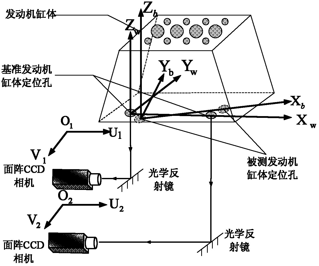
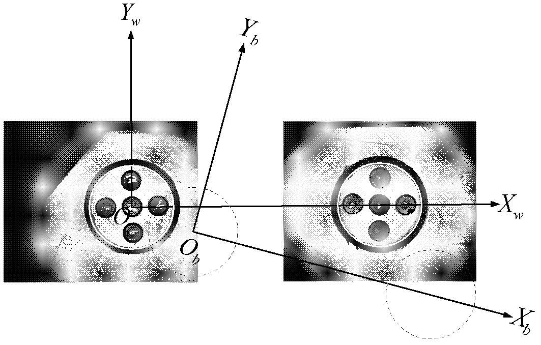
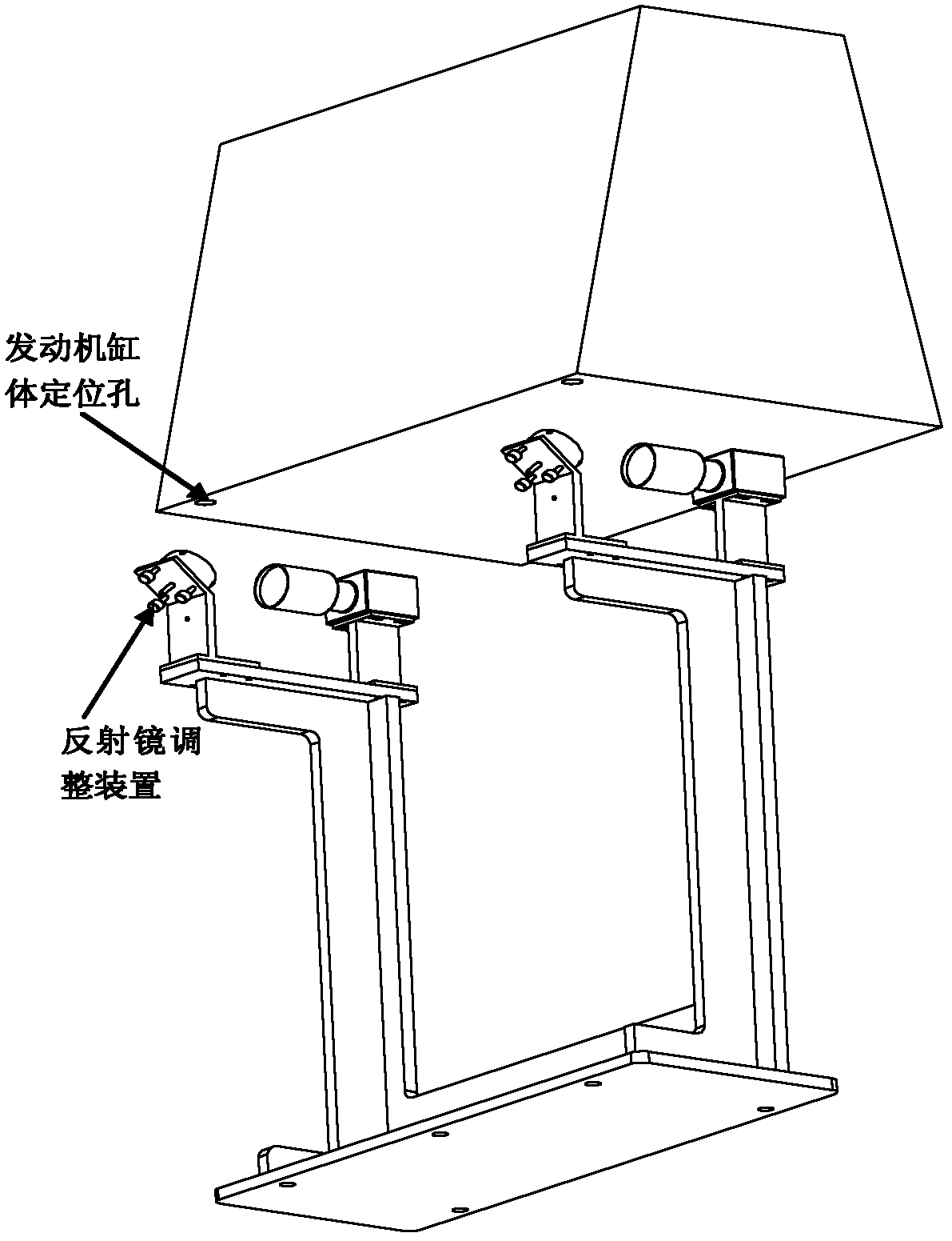
[0023] The visual positioning system designed by the present invention is composed of a double-array CCD positioning camera, an image acquisition card, a calibration target, an optical mirror, a mirror adjustment device, an LED lighting system, and a data processing computer. After the rough positioning of the engine block is completed, a high-brightness LED lighting device is used to illuminate the positioning hole of the engine block, and the image information of the two positioning pin holes of the engine block is obtained through an area array CCD camera and an optical mirror. The computer completes the acquisition of the image information of the calibration target feature hole and the positioning pin hole of the engine cylinder block under test. The center position of the positioning pin hole is extracted by image processing technology, so as to establish the measurement reference of each measured cylinder.

[0024] The positioning system positioning model is attached fi...


PUM


Abstract

The invention relates to on-line detection of a combination surface hole group of an engine cylinder. In order to meet automatic, quick and high-precision positioning requirements for a detection line of the engine cylinder, the invention adopts the technical scheme that an on-line detection vision positioning method for the combination surface hole group of the engine cylinder is implemented by a double-matrix charge coupled device (CCD) positioning camera, an image acquisition card, a calibration target, an optical reflecting mirror, a reflecting mirror adjustment device, a light emitting diode (LED) lighting system and a data processing computer and comprises the following steps of: coarsely positioning the engine cylinder; lighting positioning holes of the engine cylinder by using a high-brightness LED lighting device; acquiring the image information of two positioning pin holes of the engine cylinder by using the double-matrix CCD positioning camera and the optical reflecting mirror together; acquiring the image information of a characteristic hole of the calibration target and the positioning pin holes of the engine cylinder which is measured by using the image acquisition card and the computer; and extracting the center of each positioning pin hole by using an image processing technology. The method is mainly applicable to on-line detection of the engine cylinder.

Description

technical field [0001] The invention relates to an on-line detection of an engine block combination face group, in particular to a visual positioning method for the on-line detection of an engine block combination face group. Background technique [0002] The engine block is the positioning part of most parts in the engine. The size and position of the combined face group of the engine block are very important, directly related to the overall coupling effect of the engine, and play a vital role in the final quality of the product, which needs to be measured. The engine block joint face group is mainly divided into two categories: cylinder bore, positioning hole and coupling hole. Using positioning pin holes to complete the machining of the engine block is one of the main positioning benchmarks of the processing machine tool. The cylinder bore and connecting hole are processed under this process benchmark, so the position measurement of the engine cylinder bore and connectin...

Claims


Application Information

Patent Timeline
Patent Type & Authority Patents(China)
IPC IPC(8): G01B11/00
Inventor 孙长库段红旭石永强王鹏王宝光
Owner TIANJIN UNIV
Learn More