
A Stepping Positioning System of Calibration Mechanism

A positioning system and calibration technology, applied in measurement devices, instruments, optical devices, etc., can solve the problems of large temperature influence, inability to stop, loss of step, etc., and achieve the effect of good fault tolerance.

Active Publication Date: 2014-10-08
BEIJING RES INST OF SPATIAL MECHANICAL & ELECTRICAL TECH
View PDF2 Cites 0 Cited by
  • Summary
  • Abstract
  • Description
  • Claims
  • Application Information

AI Technical Summary

Problems solved by technology

However, this method needs to find the zero position again when powering on, and there is a risk of loss of synchronization due to increased friction during long-term operation
[0005] The traditional closed-loop positioning method generally uses photoelectric pairs for position detection, which is greatly affected by temperature, and the fault-tolerant hysteresis window is small. Motor jitter can easily cause misjudgment of the position signal, resulting in inaccurate positioning of the calibration mechanism, and even failure to stop.

Method used


Image

  • A Stepping Positioning System of Calibration Mechanism
  • A Stepping Positioning System of Calibration Mechanism
  • A Stepping Positioning System of Calibration Mechanism

Examples


Embodiment

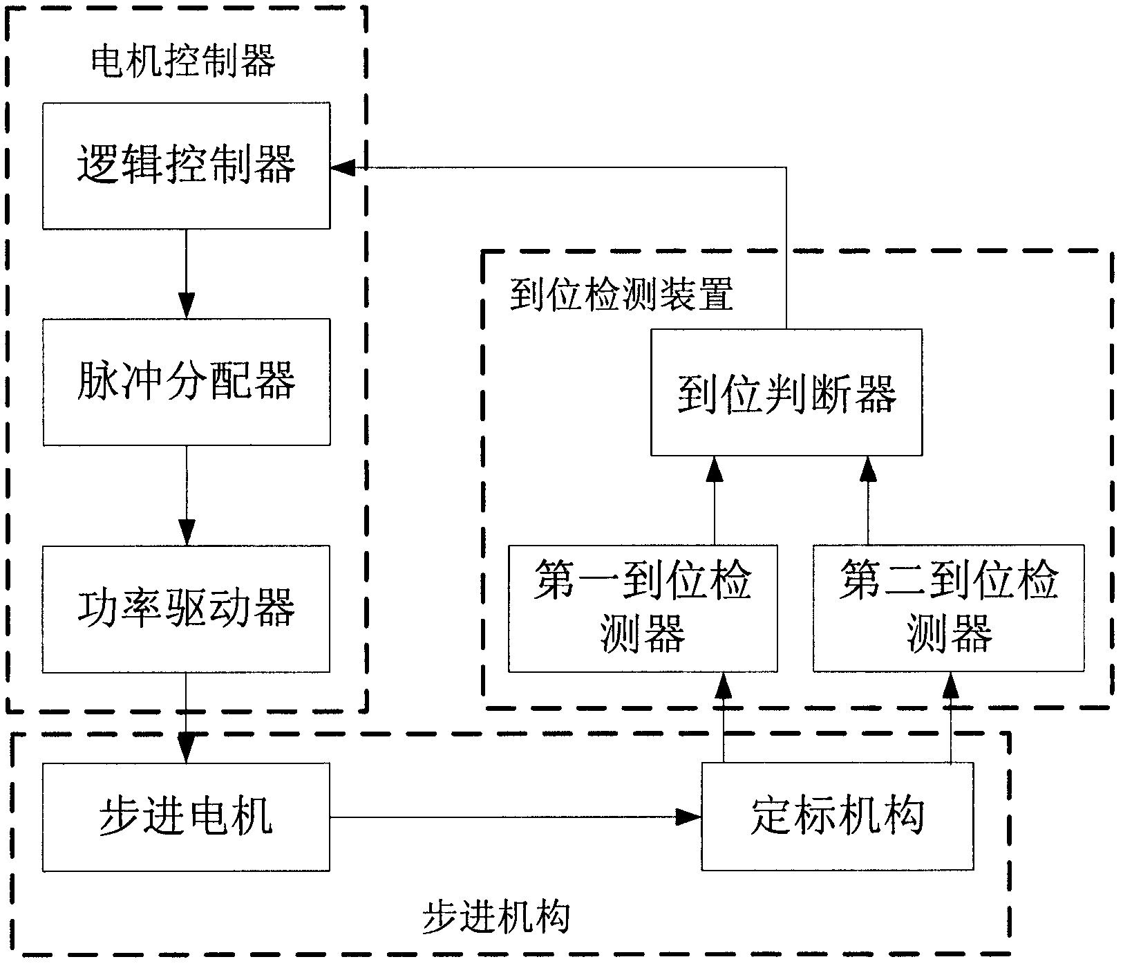
[0035] like Figure 4 As shown, the photoelectric pair D1 and Q1 are used to form the first in-position detector, D2 and Q2 are used as the second in-position detector, and the inverter 74HC14 with Schmitt trigger function is used as the in-position judger. In Fig. 5, R1=2kΩ, R2=3kΩ, R3=1kΩ, R4=4kΩ, R5=100kΩ, the hysteresis thresholds of 74HC14 are 1.8V and 2.8V respectively.

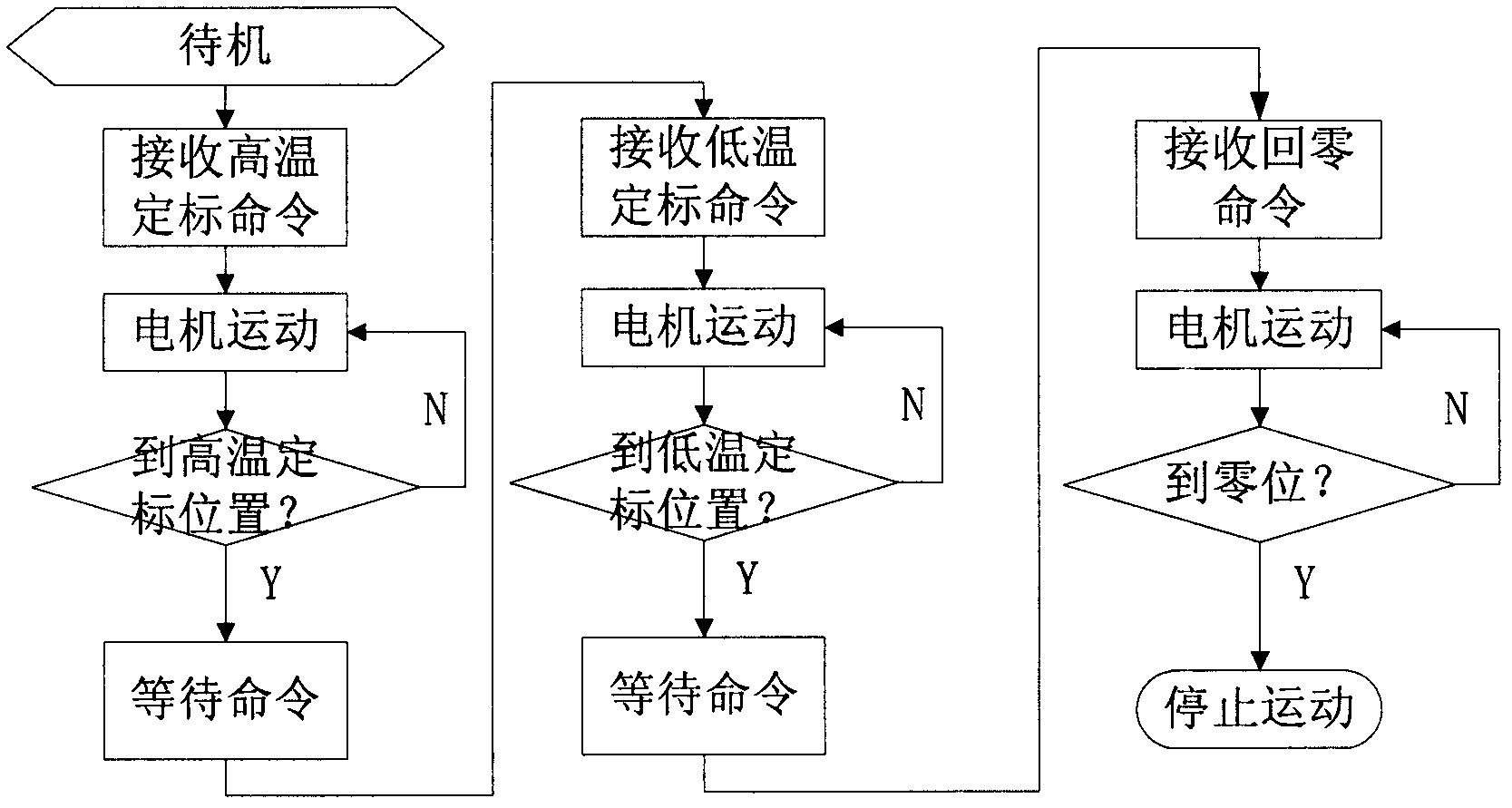
[0036] a. The motor controller receives the command from the upper computer, and controls the stepper motor to drive the calibration mechanism to move toward the positioning position;

[0037] b. When the calibration mechanism moves to position 1, the photoelectric pair D1, Q1, D2, and Q2 are all turned on, the collectors of Q1, Q2 output (0.3V, 0.3V), the voltage at the input terminal of T1 is 0V, and the output of T2 If the switching value is 0, the calibration mechanism will continue to move;

[0038] c. When the calibration mechanism moves from position 1 to position 2 (the first calibration posit...


PUM


Abstract

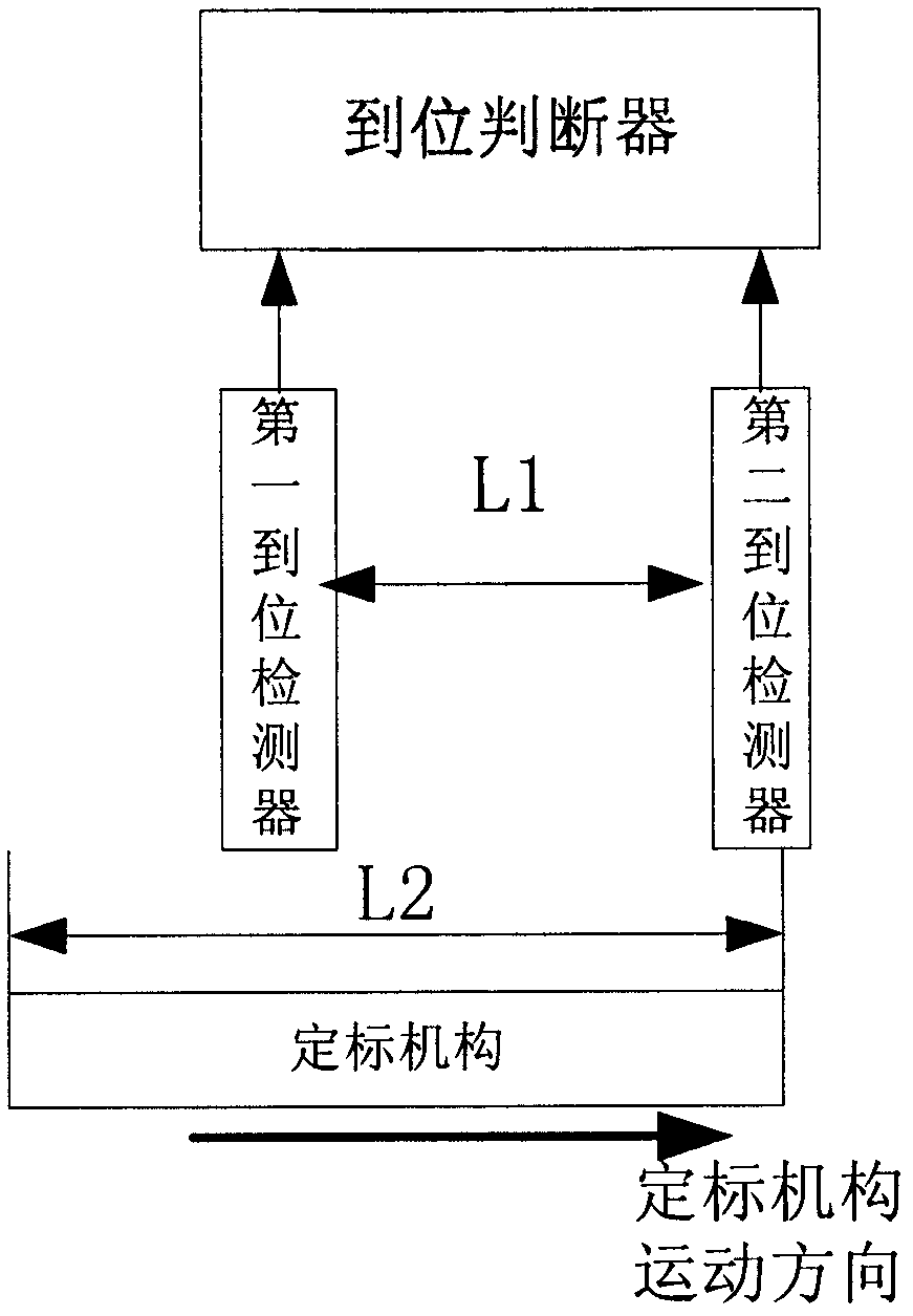
The invention discloses a stepping positioning system for a calibration mechanism. The stepping positioning system comprises a motor controller, a stepping mechanism and an in-place detection device. The stepping mechanism comprises a stepping motor which is used for driving the calibration mechanism to move; the in-place detection device comprises a first in-place detector, a second in-place detector and an in-place judger, wherein the first in-place detector is used for judging whether the calibration mechanism reaches a first calibration position or not and outputting an indication signal to the in-place judger, the second in-place detector is used for judging whether the calibration mechanism reaches a second calibration position or not and outputting an indication signal to the in-place judger, and according to the indication signals outputted by the first in-place detector and the second in-place detector, the in-place judger generates an in-place indication signal which is outputted to the motor controller; and the motor controller controls the movement or stoppage of the stepping motor of the stepping mechanism according to the received in-place indication signal. The stepping positioning system for the calibration mechanism has the advantages that: the calibration mechanism can be reliably and accurately positioned under the drive of the stepping motor.

Description

technical field [0001] The invention relates to a step positioning system of a calibration mechanism. Background technique [0002] In the field of space infrared remote sensing imaging, in order to ensure the imaging accuracy, it is necessary to calibrate the CCD frequently. The calibration mechanism stops at the 0° position at the non-calibration moment, and the high and low temperature black bodies are not in the imaging optical path; when calibration is required, the stepper motor first drives the calibration mechanism to move to the 45° position for high temperature calibration, and then moves to 90° ° position for low-temperature calibration, after the calibration is completed, the calibration mechanism directly returns to the 0 ° position from the 90 ° position, and does not stay at the 45 ° position. [0003] At present, the commonly used calibration mechanism positioning methods include: pulse counting step positioning method, in-position closed-loop positioning me...

Claims


Application Information

Patent Timeline
Patent Type & Authority Patents(China)
IPC IPC(8): G01B21/00G01B11/00
Inventor 金占雷刘雪峰
Owner BEIJING RES INST OF SPATIAL MECHANICAL & ELECTRICAL TECH
Learn More