
Split large screen-based multi-target optical fiber positioning simulation calibration method and equipment

A technology of optical fiber positioning and analog calibration, applied in the direction of instruments, etc., can solve the problems of inability to accurately and conveniently test the movement of the positioning unit mechanism, difficulty in verifying and judging the positioning accuracy of optical fibers, and inability to verify the positioning accuracy of optical fibers, etc., to achieve a clear principle, The effect of simple structure and high precision calibration

Active Publication Date: 2014-05-28
NANJING INST OF ASTRONOMICAL OPTICS & TECH NAT ASTRONOMICAL OBSE
View PDF4 Cites 0 Cited by
  • Summary
  • Abstract
  • Description
  • Claims
  • Application Information

AI Technical Summary

Problems solved by technology

The conventional optical fiber positioning and calibration test uses the photographic method. After the large focal plane is divided into small areas, the optical fiber end face is photographed and calibrated with the backlight of the optical fiber. The final splicing combination adopts polynomial fitting, but in the actual site, it will be additionally affected by the positioning unit mechanism. , camera attitude, camera position change, camera error, image quality, seeing, optical fiber properties, focal plane temperature deformation, focal plane gravity deformation, partition splicing, plane and spherical coordinate conversion, etc. Positioning accuracy is difficult to truly verify and judge
[0004] With the development of multi-objective spectral surveys and the increasing number of units and precision requirements, the disadvantages of the current photographic method using optical fiber backlighting (active illumination at the far end of optical fiber) are: it will be affected by factors such as camera attitude, camera position change, camera Error, image quality, positioning unit mechanism, seeing degree, optical fiber properties, focal plane geometry, focal plane temperature deformation, focal plane gravity deformation, partition splicing, plane and spherical coordinate conversion, etc., cannot be accurate and accurate Conveniently test the movement of the positioning unit mechanism and cannot verify the positioning accuracy of all optical fibers

Method used


Image

  • Split large screen-based multi-target optical fiber positioning simulation calibration method and equipment
  • Split large screen-based multi-target optical fiber positioning simulation calibration method and equipment
  • Split large screen-based multi-target optical fiber positioning simulation calibration method and equipment

Examples


Embodiment 1

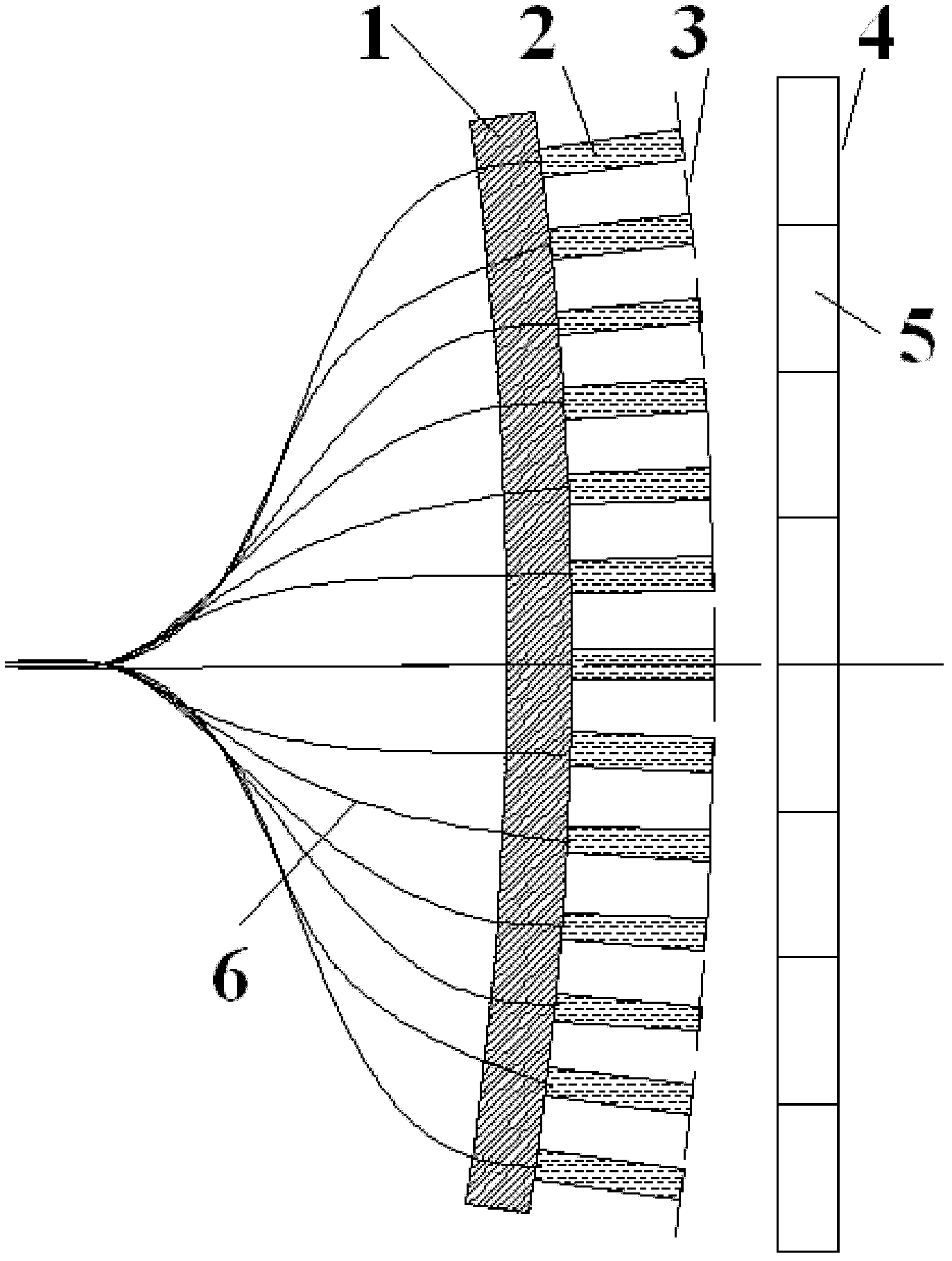
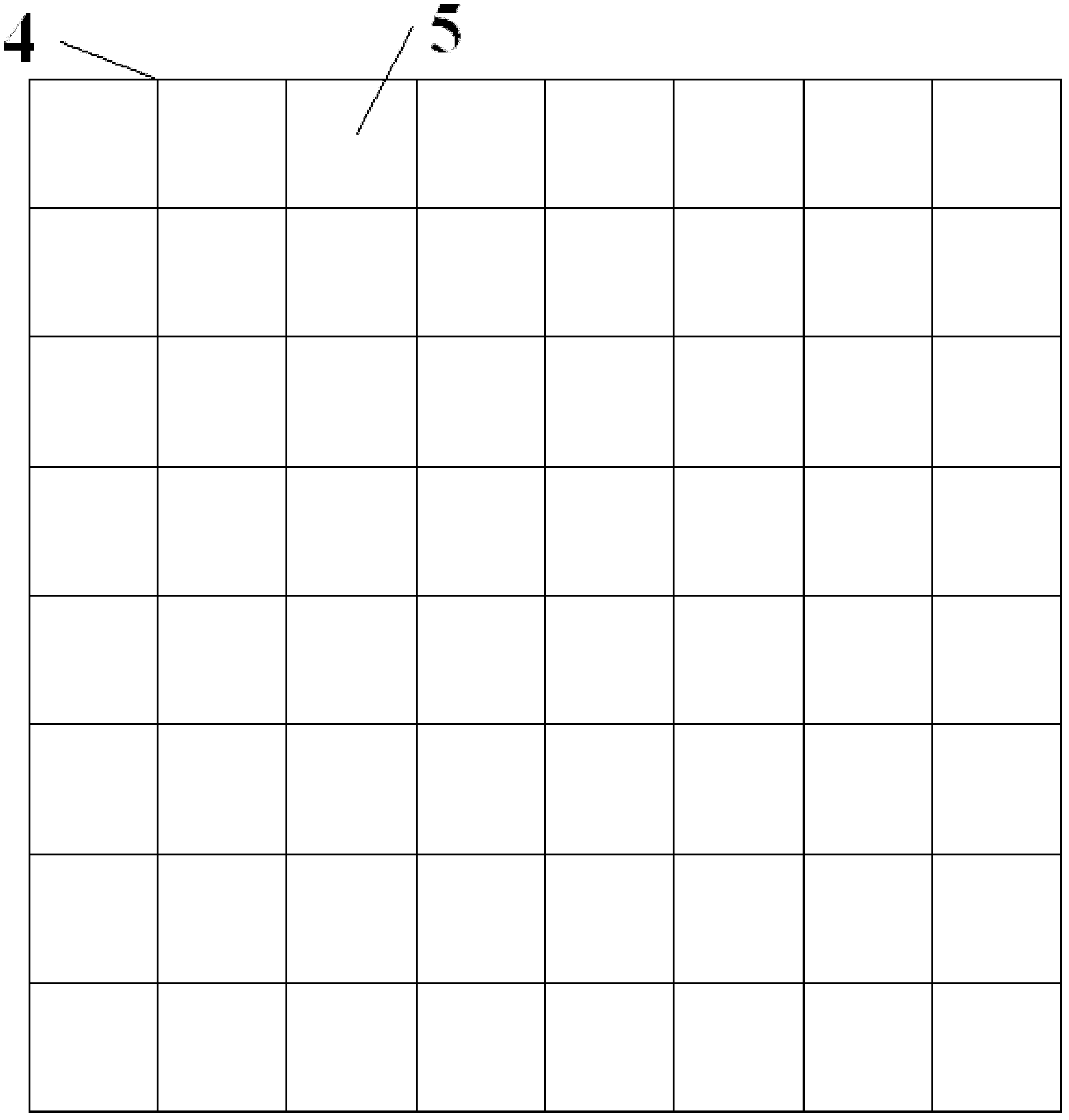
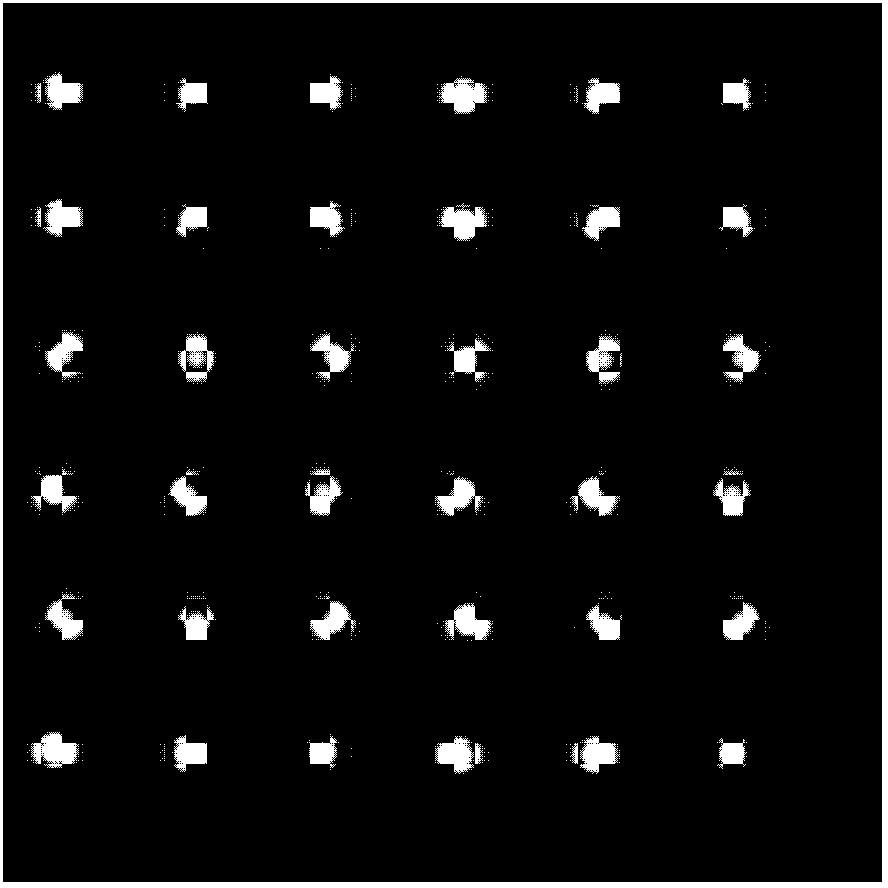
[0026] Embodiment 1, multi-objective optical fiber positioning simulation method based on splicing large screens, in figure 1 Among them, the antenna detection system includes a focal plane base plate 1, an optical fiber positioning unit 2, a virtual theoretical focal plane 3, a spliced ​​large screen 4, a small screen unit 5 and a light-transmitting optical fiber 6; figure 2 For spliced ​​large screen; image 3 It is the astronomical observation target source simulated and displayed on the large screen; Figure 4 and Figure 5 are respectively two active alignment and calibration methods, which include the fiber end face 7 and the astronomical spectrum target source 8, and FIG. Fig. 8 shows the active movement of the optical fiber positioning unit mechanism in a small range to realize two-dimensional scanning of the optical fiber end face.

[0027] The splicing large screen fixed in front of the focal plane can be a large screen spliced ​​by small liquid crystal or plasma...


PUM


Abstract

The invention discloses a split large screen-based multi-target optical fiber positioning simulation calibration method and equipment. The method comprises the following steps of: (1) setting a split large screen in front of a multi-target optical fiber positioning system; (2) directly measuring the overall large screen, and calibrating the mutual spatial position coordinates of each display unit in a large-screen coordinate system; (3) simulating and generating an astronomical spectrum observation target corresponding to an optical fiber on the large screen, and ordering the optical fiber positioning system to realize positioning according to the geometric transformation relation between the large screen and a focal plane position; and (4) performing two-dimensional alignment scanning positioning by using an optical fiber positioning movement mechanism and a simulated astronomical spectrum observation target source, exposing and acquiring integral optical fiber spectrum energy by using a camera, and precisely calibrating the ideal position of an optical fiber positioning unit and positioning the movement precision by using the optical fiber positioning movement mechanism by acquiring the analogue Gaussian fitting of discrete energy and the position data and performing interpolation processing. The equipment is simple in structure and low in cost. The performance and precision of multi-target optical fiber positioning are improved and guaranteed in real time.

Description

Technical field [0001] The present invention involves a multi -target fiber positioning simulation method based on a large -screen large screen, which is very suitable for the multi -target fiber optic positioning of multi -target optical fiber spectrum telescopic mirror -based standard detection, positioning mechanism motion testing, and related positioning accuracy.The present invention also involves the equipment used for this multi -target optical fiber positioning method based on a large -screen large screen. Background technique [0002] Astronomy is entering a new period of booming, realizing imaging and spectral observations in the full band of space / ground.However, the understanding of the nature and behavior of the most mature celestial body and the most mature use of optical bands in optical bands, and the spectral information obtained by the tens of billions of celestial bodies obtained by the relative imaging sky patrol is still very lacking.The new multi -target opt...

Claims


Application Information

Patent Timeline
Patent Type & Authority Patents(China)
IPC IPC(8): G01D18/00
Inventor 张勇李烨平
Owner NANJING INST OF ASTRONOMICAL OPTICS & TECH NAT ASTRONOMICAL OBSE
Learn More