
Vehicle body welding spot defect detection device and method based on STFT time-frequency analysis

A technology of defect detection and time-frequency analysis, which is applied to measuring devices, analyzing materials, and analyzing solids using sound waves/ultrasonic waves/infrasonic waves, etc. It can solve problems such as low artificial timeliness and incomplete detection information, and achieve long-term detection and operation. Simple, Accuracy-Enhancing Effects

Pending Publication Date: 2020-12-04
SOUTH CHINA AGRI UNIV
View PDF0 Cites 0 Cited by
  • Summary
  • Abstract
  • Description
  • Claims
  • Application Information

AI Technical Summary

Problems solved by technology

[0003] The purpose of the present invention is to overcome the shortcoming that exists in the prior art, provide a kind of vehicle body welding spot defect detection device and method based on STFT (short-time Fourier transform) time-frequency analysis, by utilizing time-domain analysis, frequency-domain analysis and Combined with time-frequency analysis, the ultrasonic detection signal is processed and analyzed, and a more detailed time-frequency diagram can be obtained, which can accurately detect the quality of the solder joints of the car body without damage, and solve the problems of low artificial timeliness and detection in the existing technology. Solve technical problems such as incomplete information, improve detection accuracy, ensure continuous and efficient solder joint detection work, and save manpower and material resources

Method used


Image

  • Vehicle body welding spot defect detection device and method based on STFT time-frequency analysis
  • Vehicle body welding spot defect detection device and method based on STFT time-frequency analysis
  • Vehicle body welding spot defect detection device and method based on STFT time-frequency analysis

Examples


Embodiment 1

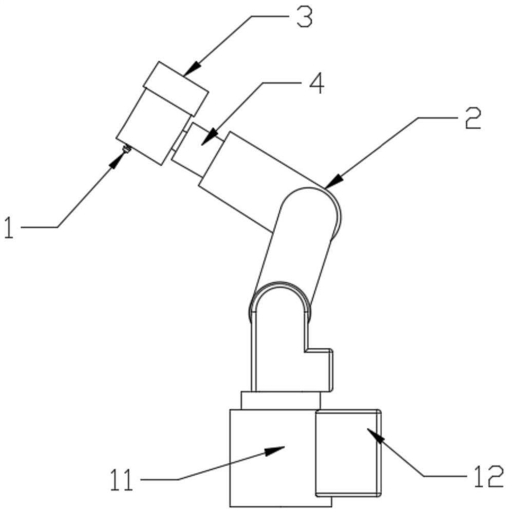
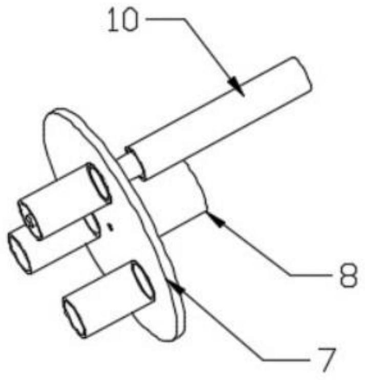
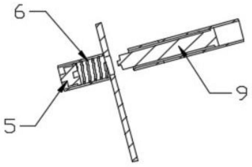
[0039] Such as figure 1 , figure 2 and image 3 As shown, a vehicle body solder joint defect detection device based on STFT time-frequency analysis includes an ultrasonic detection module 1, a six-degree-of-freedom robot 2, a hydraulic pump and a hydraulic oil reservoir 3, an ultrasonic generator 4, an ultrasonic probe 5, and a return spring 6. Rotary disk 7, motor 8, push rod 9, hydraulic cylinder 10, control module 11, upper computer 12. The ultrasonic detection module 1 is located in front of the upper part of the six-degree-of-freedom robot 2 . The hydraulic pump and hydraulic oil reservoir 3 are located behind the upper part of the six-degree-of-freedom robot 2 and are connected to the ultrasonic detection module 1 . The ultrasonic generator 4 is located at the connection between the ultrasonic detection module 1 and the six-degree-of-freedom robot 4 . The ultrasonic probe 5, return spring 6, rotating disc 7, motor 8, push rod 9, hydraulic cylinder 10, etc. are built...


PUM


Abstract

The invention discloses a vehicle body welding spot defect detection device and a method based on STFT time-frequency analysis. The device comprises an ultrasonic detection module, a six-degree-of-freedom robot, an ultrasonic generator, an ultrasonic probe, a control module and an upper computer, the ultrasonic detection module is positioned in front of the upper part of the six-degree-of-freedomrobot; the ultrasonic generator is located at the joint of the ultrasonic detection module and the six-degree-of-freedom robot. The control module is fixed in front of the lower portion of the six-degree-of-freedom robot, and the upper computer is fixed behind the lower portion of the six-degree-of-freedom robot. The upper computer can carry out noise filtering, STFT time-frequency analysis and feature extraction on specific features through a mathematical morphology-based mechanical vibration signal noise reduction method. The detection method is high in accuracy, ultrasonic reflection is used for detection and STFT-based time-frequency analysis, and the welding spot detection accuracy is improved by digitally analyzing the time-frequency relationship of ultrasonic signals.

Description

technical field [0001] The invention relates to the field of industrial detection, in particular to a detection device and method for welding spot defects of a vehicle body based on STFT time-frequency analysis. Background technique [0002] In the manufacturing process of automobile body-in-white, the main joining process is welding. Welding plays an irreplaceable and important role in automobile manufacturing, and the performance and fatigue strength of solder joints directly affect the overall performance of the automobile. In actual production, some welding defects will inevitably appear, resulting in unstable quality of solder joints, and in severe cases, there will be batches of unqualified solder joints. Therefore, when the car leaves the factory, it is necessary to test the performance of the solder joint position of each part. The existing ultrasonic flaw detector can detect the solder joints of the whole body, mainly using the difference between the solder joints ...

Claims


Application Information

Patent Timeline
Patent Type & Authority Applications(China)
IPC IPC(8): G01N29/04G01N29/12G01N29/44
CPCG01N29/04G01N29/12G01N29/4418G01N29/4472
Inventor 周锡恩毛彩云张兆宇李展通李岸立刘盛腾
Owner SOUTH CHINA AGRI UNIV
Learn More