
Digital current transformer based on induction power supply and monitoring method for digital current transformer

A technology of inductive power supply and digital current, which is applied in the direction of voltage/current isolation and measurement using digital measurement technology. It can solve the problems of affecting measurement accuracy, expensive equipment cost, and data transmission distance that cannot be transmitted over long distances, so as to improve measurement Accuracy, the effect of reducing engineering difficulty and cost

Active Publication Date: 2012-07-18
昆明迪森电气有限公司
View PDF6 Cites 13 Cited by
  • Summary
  • Abstract
  • Description
  • Claims
  • Application Information

AI Technical Summary

Problems solved by technology

The data transmission distance of this AC analog signal is too short to carry out long-distance transmission. The analog signal must be converted into a digital signal through an additional acquisition controller before long-distance transmission can be carried out. The equipment cost is relatively expensive.
In addition, due to the different degrees of attenuation of the analog signal during the transmission process due to the different lengths of the wires, it will affect the measurement accuracy
At the same time, the analog signal is susceptible to interference, which will also affect the authenticity of the measurement

Method used


Image

  • Digital current transformer based on induction power supply and monitoring method for digital current transformer
  • Digital current transformer based on induction power supply and monitoring method for digital current transformer
  • Digital current transformer based on induction power supply and monitoring method for digital current transformer

Examples


specific Embodiment

[0030] As a specific embodiment of the present invention, the CPU 20 includes a power module 202 , and the DC / DC converter 21 is electrically connected to the power module 202 . In addition, the CPU 20 also includes an analog-to-digital converter (ADC: Analog to Digital Converter) 204, an operation analysis module 206, and a CAN controller 208 electrically connected in sequence, and the sampling module 24 is electrically connected to the analog-to-digital converter 204. connection, the power module 202 is electrically connected to the analog-to-digital converter 204 , the operation analysis module 206 , and the CAN controller 208 , and the CAN transceiver 26 is electrically connected to the CAN controller. Wherein, the power supply module 202 provides power supply for the normal operation of the entire CPU20; the analog-to-digital converter 204 is used to perform analog-to-digital conversion on the received analog signal, and the operation analysis module 206 is used to perform...


PUM


Abstract

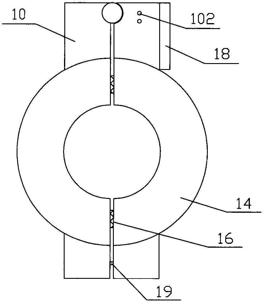
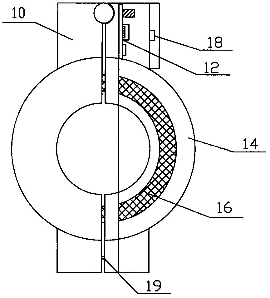
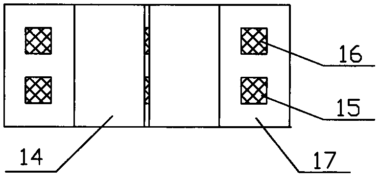
The invention discloses a digital current transformer based on induction power supply and a monitoring method for the digital current transformer. The digital current transformer based on induction power supply comprises a mounting base, a circuit board and a plastic shell and also comprises an induction electricity-taking coil arranged in the plastic shell and a detection coil, wherein a communication interface is formed on the mounting base; a central processing unit (CPU), a rectification circuit, a sampling module and a CAN transceiver are arranged on the circuit board; the rectification circuit and the sampling module are electrically connected with one end of the CPU respectively; the CAN transceiver is electrically connected with the other end of the CPU; the plastic shell comprises two semi-circular shells which are arranged in a matched manner; the induction electricity-taking coil and the detection coil adopt opening / closing type iron cores; the induction electricity-taking coil is electrically connected with the rectification circuit; the detection coil is electrically connected with the sampling module; and the communication interface is electrically connected with the CAN transceiver. Electricity is supplied by induction current instead of external power supply, and digital signals are directly output without an acquisition controller, so that the measurement accuracy is improved and the engineering cost can be greatly reduced.

Description

technical field [0001] The invention relates to a current transformer, in particular to an integrated digital current transformer based on inductive power supply and a method for monitoring cables. Background technique [0002] Transformer is a device that converts voltage or current in proportion. Its function is to convert high voltage or high current into standard low voltage or standard small current in proportion, so as to realize the standardization and miniaturization of measuring instruments, protection equipment, and automatic control equipment. . In addition, transformers can also be used to isolate high-voltage systems to ensure the safety of people and equipment. A current transformer is a component that performs current conversion based on the principle of electromagnetic induction. It is widely used in power systems and plays the role of current conversion and electrical isolation. [0003] The currently used current transformers are generally of the wiring t...

Claims


Application Information

Patent Timeline
IPC IPC(8): G01R15/18G01R19/25
Inventor 唐立文吴梦江王明勇
Owner 昆明迪森电气有限公司
Learn More