Resistance measuring circuit

一种电阻测定、电源电路的技术,应用在电路装置、测量电阻/电抗/阻抗、紧急保护电路装置等方向,能够解决操作不便、浪费人力和时间、效率低等问题,达到操作方便、节省人力和时间的效果

Inactive Publication Date: 2012-07-18
HONG FU JIN PRECISION IND (SHENZHEN) CO LTD +1
View PDF3 Cites 2 Cited by
  • Summary
  • Abstract
  • Description
  • Claims
  • Application Information

AI Technical Summary

Problems solved by technology

This method needs to continuously weld different resistors to the power supply circuit for testing, which is inconvenient to operate, wastes a lot of manpower and time, and is inefficient

Method used


Image

  • Resistance measuring circuit
  • Resistance measuring circuit
  • Resistance measuring circuit

Examples


Embodiment Construction

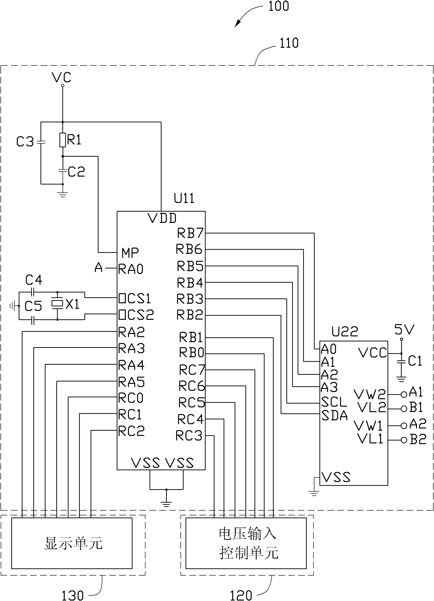
[0030] see figure 1 The resistance measurement circuit 100 of the present invention includes a resistance setting unit 110 , a voltage input control unit 120 and a display unit 130 .

[0031] The resistance setting unit 110 includes a microcontroller U11, a digital potentiometer U22, a resistor R1, five capacitors C1, C2, C3, C4 and C5, and a crystal oscillator X1. The first voltage terminal VDD of the single-chip microcomputer U11 is connected to a voltage source VC and grounded sequentially through the resistor R1 and the capacitor C2, and the capacitor C3 is connected in series between the voltage source VC and the ground. The second voltage terminal MP of the single-chip microcomputer U11 is connected to a node between the resistor R1 and the capacitor C2. The first clock terminal OCS1 of the single-chip microcomputer U11 is grounded through the capacitor C4, the second clock terminal OCS2 is grounded through the capacitor C5, and the crystal oscillator X1 is connected in...


PUM


Abstract

The invention relates to a resistance measuring circuit for measuring a power supply circuit. The power supply circuit comprises a voltage collecting circuit and an input overvoltage protective circuit. The voltage collecting circuit is connected to an external voltage. The input overvoltage protective circuit is provided with a comparator. Two first incoming ends are arranged between the positive input end of the comparator and the external voltage of the comparator. The resistance measuring circuit comprises a voltage input control unit, a single chip, a digital potentiometer and a display unit. The digital potentiometer comprises a first rheostat. Both ends of the rheostat are respectively connected to the two first incoming ends. The voltage input control unit is used for setting an input overvoltage for the single chip. The single chip is used for measuring and comparing the external voltage. When the external voltage is equal to the input overvoltage, the singlechip adjusts the first rheostat to a first critical value. The digital potentiometer feeds the first critical value to the single chip and transmits the first critical value to the display unit to display. The invention can rapidly determine the first critical value, particularly, the resistance connected to the two first incoming ends.

Description

technical field [0001] The invention relates to a resistance measuring circuit. Background technique [0002] Existing power supply circuits generally include an input overvoltage protection circuit. When the input voltage of the power circuit reaches an input overvoltage, the input overvoltage protection circuit works, and the power circuit stops working. And when the input voltage of the power supply circuit drops from the input overvoltage to an input overvoltage recovery voltage, the input overvoltage protection circuit stops functioning, and the power supply circuit resumes working. Generally, the input overvoltage protection circuit includes an input resistor and a feedback resistor. [0003] In the design of the power supply circuit, the input overvoltage and input overvoltage recovery voltage of the power supply circuit are first determined according to the design requirements, and then the resistance values ​​of the input resistance and the feedback resistance are...

Claims


Application Information

Patent Timeline
Patent Type & Authority Applications(China)
IPC IPC(8): G01R27/02
CPCG01R27/02H02H9/04H02H3/20H02H3/006
Inventor 童松林陈鹏罗奇艳
Owner HONG FU JIN PRECISION IND (SHENZHEN) CO LTD
Why Eureka
Try Eureka