
Communication capacity test device of intelligent carrier electrical energy meters and test method thereof

A capability test and electric energy meter technology, applied in the direction of measuring devices, measuring electricity, measuring electrical variables, etc., can solve the problems of inaccurate test results, difficulty in distinguishing, carrier influence, etc., achieve accurate and reliable test results, promote practical level, The effect of simple overall structure

Active Publication Date: 2012-07-18
STATE GRID HEBEI ELECTRIC POWER RES INST +2
View PDF3 Cites 5 Cited by
  • Summary
  • Abstract
  • Description
  • Claims
  • Application Information

AI Technical Summary

Problems solved by technology

Otherwise, when the carrier communication cannot be carried out normally, it is impossible to judge the problem, because it may be a failure of the energy meter or a problem of the line, especially a failure of the meter end, which often leads to failure to obtain useful power consumption information.
The problem at the meter end may exist before leaving the factory, or it may be caused during use, and it is often difficult to distinguish
[0003] The single-phase isolation PT of the traditional single-phase carrier test device has a great influence on the carrier, and the test results are not accurate. Based on the above problems, there is an urgent need for a carrier communication function test method and instrument, which is used for the smart carrier energy meter before leaving the factory. lab testing

Method used


Image

  • Communication capacity test device of intelligent carrier electrical energy meters and test method thereof
  • Communication capacity test device of intelligent carrier electrical energy meters and test method thereof
  • Communication capacity test device of intelligent carrier electrical energy meters and test method thereof

Examples


Embodiment Construction

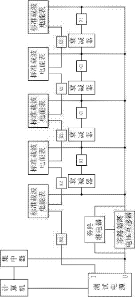
[0029] See attached figure 1 , the intelligent carrier energy meter communication ability testing device of the present invention comprises computer, test bench body and the concentrator that is installed on the test bench body, and test power supply is installed on the test bench body, and concentrator is connected on the voltage output terminal of test power supply, and computer The current commonly used centralized meter reading system management software and test power control software are installed on it, and the computer is connected to the concentrator and the test power supply respectively; four attenuators and five standard carrier energy meters are also installed on the test bench body, The current terminals of the five standard carrier energy meters are sequentially connected in series on the current output terminals of the test power supply, and a relay is connected between the current terminals of two adjacent standard carrier energy meters, and the current termina...


PUM


Abstract

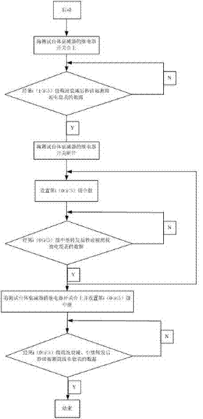
The invention discloses a communication capacity test device of intelligent carrier electrical energy meters and a test method thereof. The communication capacity test device comprises a computer, a test table body and a concentrator mounted on the test table body; four attenuators and five standard carrier electrical energy meters are mounted on the test table body; the current output end of a test power source is connected in series with the current end of the electrical energy meters through relays, and the voltage output end of the test power source supplies voltage to the electrical energy meters through a multipath isolation voltage mutual inductor which is provided with a bypass relay; and the attenuator and the relay are connected between the voltage ends of each two adjacent electrical energy meters. The attenuation of each attenuator to signals is equal to the attenuation of transmitting a carrier in an actual route for 500 m. The test method comprises a carrier attenuation test, a relay transmission test and a combined carrier attenuation and relay transmission test. With the adoption of the test device and the test method provided by the invention, a test system in a lab is completed aiming to the outstanding problems occurring in situ, so that a test result is accurate and reliable, and an entire structure is simpler.

Description

technical field [0001] The invention relates to an electric power test method and device, in particular to a single-phase and three-phase intelligent carrier wave electric energy meter communication capability laboratory test device and method thereof. Background technique [0002] Low-voltage power line carrier communication has become the main communication method for the State Grid Corporation of China to build an electricity information collection system. This technology does not need to modify the existing power grid. It only needs to install a special carrier communication chip on the concentrator and each electric energy meter. The ready-made power line carries on the carrier communication to complete the meter reading work. The carrier communication chip is directly installed in the existing carrier energy meter, but the carrier communication function of the carrier energy meter needs to be tested and verified before use. This test and verification may be carried out...

Claims


Application Information

Patent Timeline
Patent Type & Authority Applications(China)
IPC IPC(8): G01R31/00G08C19/00H04B3/54
Inventor 牛春霞耿建坡王永辉史轮陶鹏王俊龙马红明李翀冯波
Owner STATE GRID HEBEI ELECTRIC POWER RES INST
Learn More