
Constant current source circuit with band-gap reference function

A constant current source, reference source technology, applied in the direction of adjusting electrical variables, control/regulating systems, instruments, etc., can solve the problems of sensitive power supply voltage changes, large temperature coefficient, etc., to achieve the effect of reducing temperature coefficient and high performance requirements

Inactive Publication Date: 2012-07-18
NO 24 RES INST OF CETC
View PDF6 Cites 17 Cited by
  • Summary
  • Abstract
  • Description
  • Claims
  • Application Information

AI Technical Summary

Problems solved by technology

[0004] The present invention provides a constant current source circuit with the function of a bandgap reference source to overcome the problems of sensitivity to power supply voltage changes and large temperature coefficients in traditional constant current source circuits, so as to meet the high requirements of micro-power consumption and low-dropout linear power supplies. performance requirements

Method used


Image

  • Constant current source circuit with band-gap reference function
  • Constant current source circuit with band-gap reference function
  • Constant current source circuit with band-gap reference function

Examples


Embodiment Construction

[0024] The specific implementation manners of the present invention are not limited to the following description, and are now further described in conjunction with the accompanying drawings.

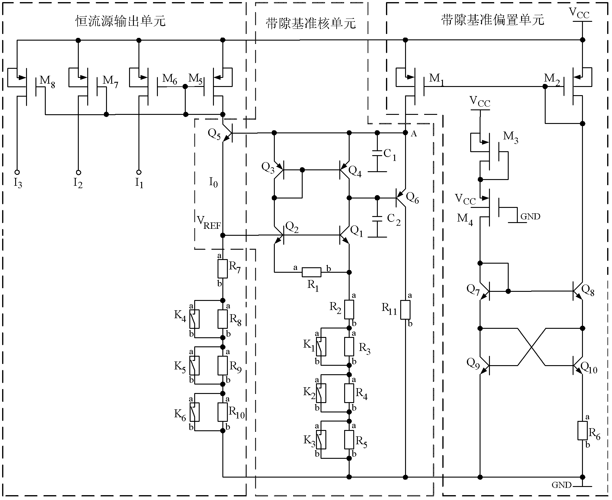
[0025] The circuit diagram of the constant current source circuit with bandgap reference function of the present invention is as image 3 As shown, the circuit of the present invention is composed of a bandgap reference core unit, a bandgap reference bias unit and a constant current source output unit. Among them, the bandgap reference bias unit provides bias current for the bandgap reference core unit, the bandgap reference core unit provides reference voltage for the constant current source output unit, and the constant current source output unit adjusts the constant current source current through the fuse trimming switch , to achieve the purpose of controlling the quiescent current of the entire circuit.

[0026] In the bandgap reference core unit, Q 1 , Q 2 The collectors of the e...


PUM


Abstract

The invention relates to a constant current source circuit with a band-gap reference function, comprising a band-gap reference core unit, a band-gap reference bias unit and a constant current source output unit, wherein the band-gap reference bias unit is used for providing bias current to a band-gap reference core; the band-bap reference core unit is used for providing band-gap reference voltage with a certain temperature coefficient to the constant current source output unit; and by combining a fuse wire trimming structure of the constant current source output unit, current of a whole constant current source branch can be adjusted. Through adjusting the temperature coefficient of the band-gap reference voltage to be matched with a temperature coefficient of resistance of the constant current source output unit, constant current source current which is insensitive to supply voltage and temperature is obtained. The constant current source circuit is applied to linear power supplies with micro power consumption and low voltage difference to ensure that the temperature coefficient of static current of the linear power supplies with low voltage difference is less than 50 ppm / DEG C, and the rejection ratio of the supply voltage is greater than 60 dB. The constant current source circuit can be applied to the field of linear power supplies with micro power consumption and low voltage difference.

Description

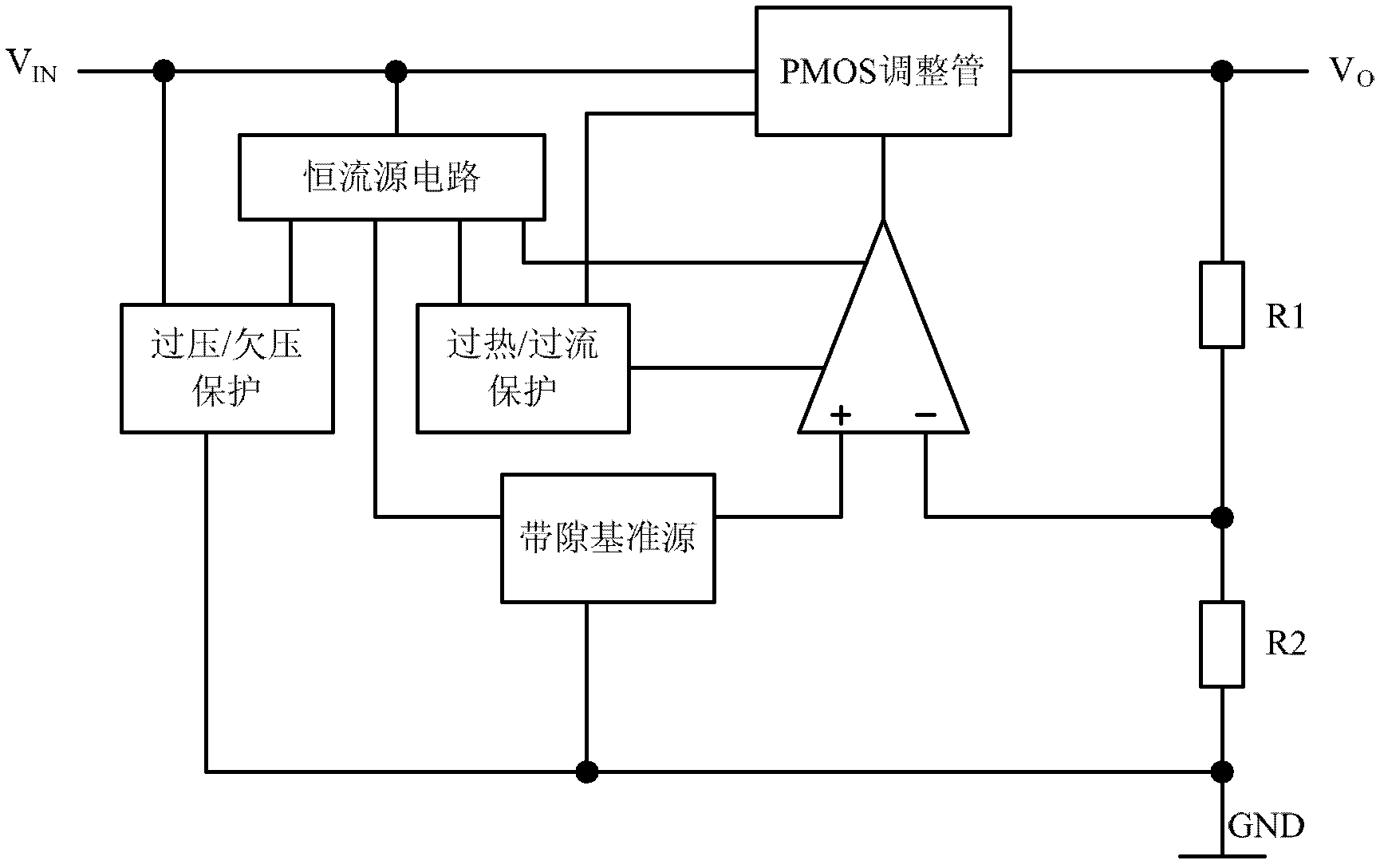
technical field [0001] The invention relates to a constant current source circuit, in particular to a constant current source circuit with the function of a bandgap reference source, which is directly applied to the field of micro-power consumption and low-dropout linear power supplies. Background technique [0002] The constant current source circuit is the core unit of the low dropout linear power supply, especially the constant current source circuit with bandgap reference performance, which is applied to the micro power consumption low dropout linear power supply. figure 1 It is a circuit block diagram of a traditional micro-power low-dropout linear power supply, which consists of bandgap reference source, error amplifier, PMOS regulator, constant current source circuit, over / undervoltage protection, over / undercurrent protection and other unit circuits. The constant current source circuit provides bias current for the error amplifier, bandgap reference source, over / under...

Claims


Application Information

Patent Timeline
IPC IPC(8): G05F1/56G05F1/567
Inventor 胡永贵胡刚毅陈光炳李儒章
Owner NO 24 RES INST OF CETC
Learn More