
Image processing device and image processing method

An image processing device and image processing technology, applied in image data processing, details involving image processing hardware, image memory management, etc.

Inactive Publication Date: 2012-07-18
SONY CORP
View PDF7 Cites 9 Cited by
  • Summary
  • Abstract
  • Description
  • Claims
  • Application Information

AI Technical Summary

Problems solved by technology

Therefore, although the problems related to the reduction of the bus frequency band are solved, the problems related to the storage capacity and power consumption are newly raised

Method used


Image

  • Image processing device and image processing method
  • Image processing device and image processing method
  • Image processing device and image processing method

Examples


Embodiment Construction

[0058] An example of an embodiment of the present disclosure is described below in the following order:

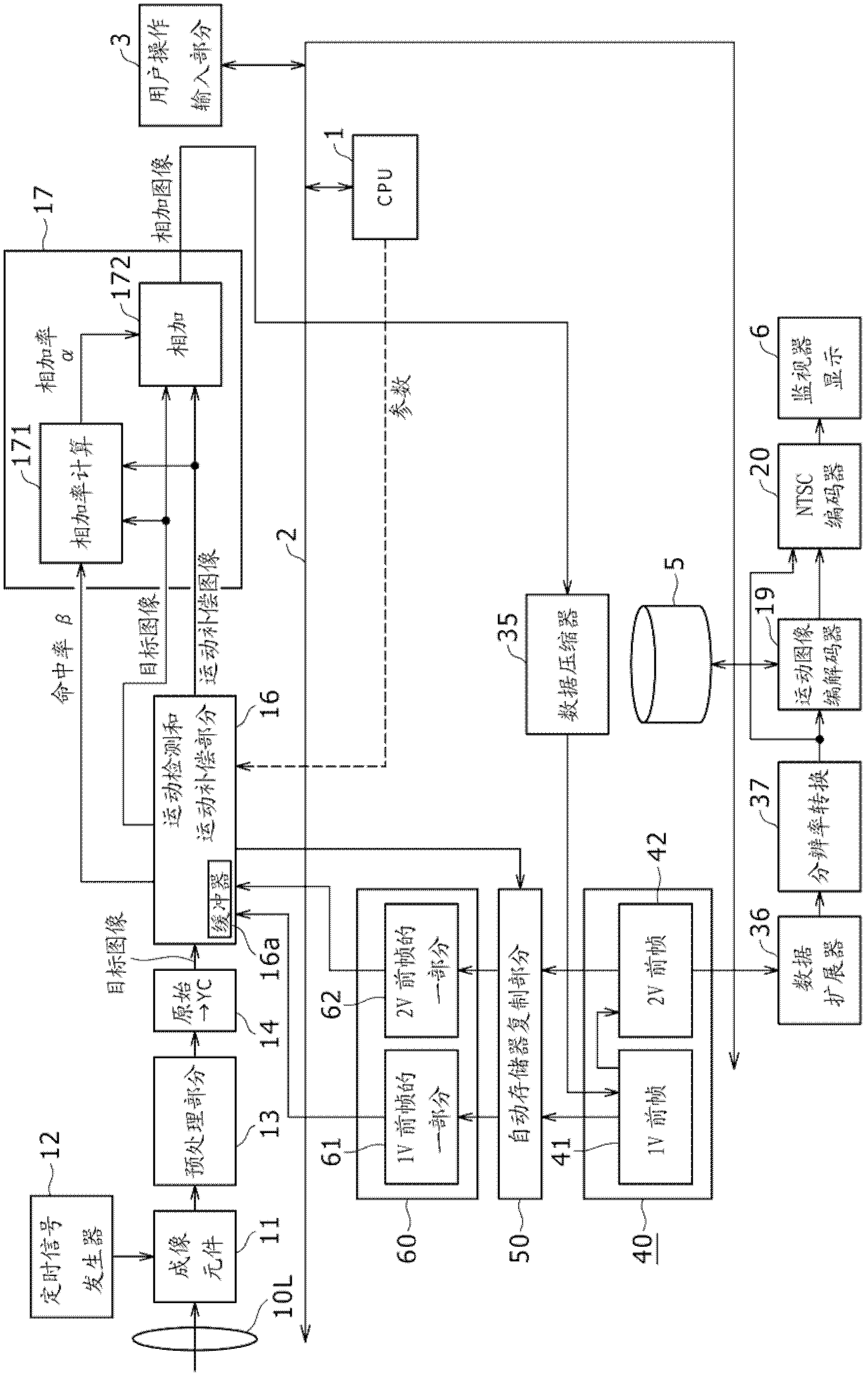
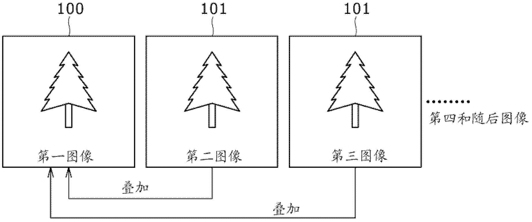
[0059] 1. Configuration of imaging equipment ( figure 1 , image 3 , Figure 4 );

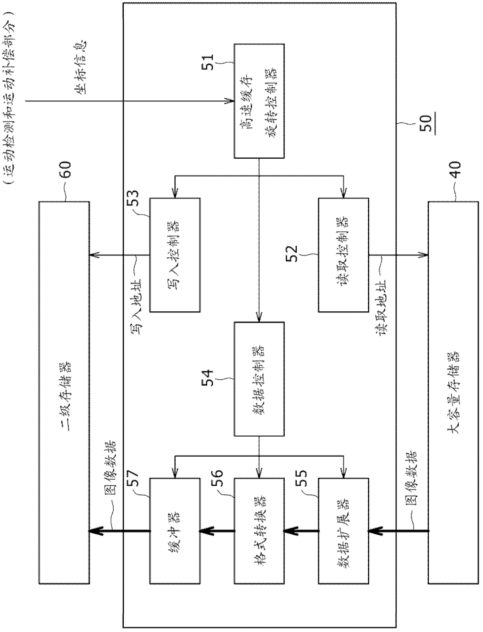
[0060] 2. The configuration of the memory copy part ( figure 2 );

[0061] 3. Description of motion detection and motion compensation part ( Figures 5 to 12 );

[0062] 4. The flow of the noise reduction processing of the captured image ( Figures 13 to 15 );

[0063] 5. Example of the flow of hierarchical block matching processing ( Figure 16 and 17 );

[0064] 6. Description of the format on the memory ( Figure 18A to Figure 30 );as well as

[0065] 7. Description of processing utilizing secondary memory ( Figure 31 to Figure 38 ).

[0066] [1. Configuration of imaging device]

[0067] An image processing apparatus according to an embodiment of the present disclosure will be described below taking an imaging apparatus as an example with reference to the accompanying dr...


PUM


Abstract

An image processing device includes an image processor that calculates a motion vector between image data of a target frame and image data of a reference frame in units of a block, and a reference frame image memory that retains image data of a past frame as the image data of the reference frame. Furthermore, the image processing device includes a primary memory that retains a matching processing range of the reference frame in calculation by the image processor, and a secondary memory that reads out and retains image data of a desired range from the image data of the reference frame stored in the reference frame image memory. The secondary memory reads out data of the matching processing range from the retained image data and supplies the read data to the primary memory.

Description

technical field [0001] The present disclosure relates to an image processing apparatus and an image processing method in which an image storage section and various image processors are connected via a system bus, and the various image processors perform respective types of image data processing by accessing the image memory. Background technique [0002] The block matching technique of obtaining the motion vector between two screens from the image information itself is an old technique. Developments have been made mainly in pan and tilt detection and object tracking of television cameras, and motion picture coding in the Moving Picture Experts Group (MPEG) system. Moreover, since the early 1990s, various technologies based on image superposition are being applied, such as sensorless camera shake correction and noise removal (noise reduction, hereinafter denoted as NR) in low-light shooting. [0003] Block matching is a method of calculating a motion vector between two scree...

Claims


Application Information

Patent Timeline
Patent Type & Authority Applications(China)
IPC IPC(8): G06T1/20G06T1/60H04N19/50H04N19/105H04N19/136H04N19/176H04N19/196H04N19/423H04N19/426H04N19/503H04N19/51H04N19/53H04N19/59H04N19/80
CPCG06T1/60G06T1/20H04N19/006H04N19/00515G06T2200/28G06T7/2013H04N7/32G06T7/223H04N19/433H04N19/53
Inventor 沼田怜
Owner SONY CORP
Learn More